Pulsed acoustic wave dermal clearing system and method

a technology of acoustic waves and dermal clearing, which is applied in the field of therapeutic use of shock waves, can solve the problems of large ttpt, unpredictability of tissue damage from shockwaves at pulse rates between 1 hz and 10 hz, and potentially impractical for many patients and treatment needs

Pending Publication Date: 2020-07-02
SOLITON
View PDF4 Cites 22 Cited by
  • Summary
  • Abstract
  • Description
  • Claims
  • Application Information

AI Technical Summary

Benefits of technology

[0030]Embodiments of the present methods, apparatuses, and systems can be configured to provide dermal clearing by dispersing and / or eliminating dermal vacuoles located superficially and / or deeper in the dermis (e.g. adjacent to pigment particle agglomerations), as well as vacuoles in the epidermis. The present methods, apparatuses, and systems can thereby enable more effective repeated laser treatments over the same treatment area in quick succession.

Problems solved by technology

Prior art literature has indicated that faster pulse rates using EH systems to provide shockwaves can lead to tissue damage.
As a result, potential damage to tissue from shockwaves at pulse rates between 1 Hz and 10 Hz is unpredictable when typical lithotripsy power levels are used.
When, as may be typical, a treatment requires repositioning of a device at multiple treatment sites, the TTPT becomes large and potentially impractical for many patients and treatment needs.
While long treatment times may be acceptable for extracorporeal shockwave lithotripsy, the use of shockwaves to provide non-lithotripsy therapeutic effects on tissue in the medical setting is less than optimal if not impractical.
For example, the cost of treatment often increases with the time needed to administer a treatment (e.g., due to the labor, facilities and other resource costs allocated to the administration of the treatment).
Furthermore, in addition to costs, at some point the duration of providing treatment to the patient becomes unbearable for the patient receiving, and healthcare staff providing, the treatment.
The authors of another paper (Freund, Colonius, & Evan, 2007) [4 9 hypothesize that the cumulative shear of the many shocks is damaging, and that the mechanism may depend on whether there is sufficient time between shocks for tissue to relax to the unstrained state.
Conversely, damage should increase for faster delivery rates.
The body's natural reaction to each of these treatments present challenges to the efficacy of the treatment.
For example, in the context of tattoo removal, exposure of a tattooed area to a laser output currently creates a “whitening” condition within the treatment area that tends to reduce the effectiveness of subsequent laser exposures.
The dermal vacuoles associated with whitening result in the attenuation or scattering of laser light resulting in loss of the lasers effectiveness after the initial treatment.
Furthermore, the dermal vacuoles remain in the skin for a period of time limiting the effectiveness of subsequent laser exposures in the same session
Whitening is problematic at least in part because the presence of dermal vacuoles in the treatment area caused by the first laser pass may attenuate or weaken the delivery of light in one or more subsequent laser passes.
Thus, vacuole presence reduces laser therapy effectiveness.
However, after a single laser treatment of the tattoo site, the laser is no longer effective for aforementioned reasons.
For a busy practice, this approach is not practical since it requires the patient to be in the office for long periods of time.
Unfortunately, PFD has very poor dermal penetration.
Thus, while PFD provides benefits in reducing the appearance of whitening, it only provides limited benefit in improving the effectiveness of repeated laser treatments to the tattoo site.

Method used


Image

  • Pulsed acoustic wave dermal clearing system and method
  • Pulsed acoustic wave dermal clearing system and method
  • Pulsed acoustic wave dermal clearing system and method

Examples


first embodiment

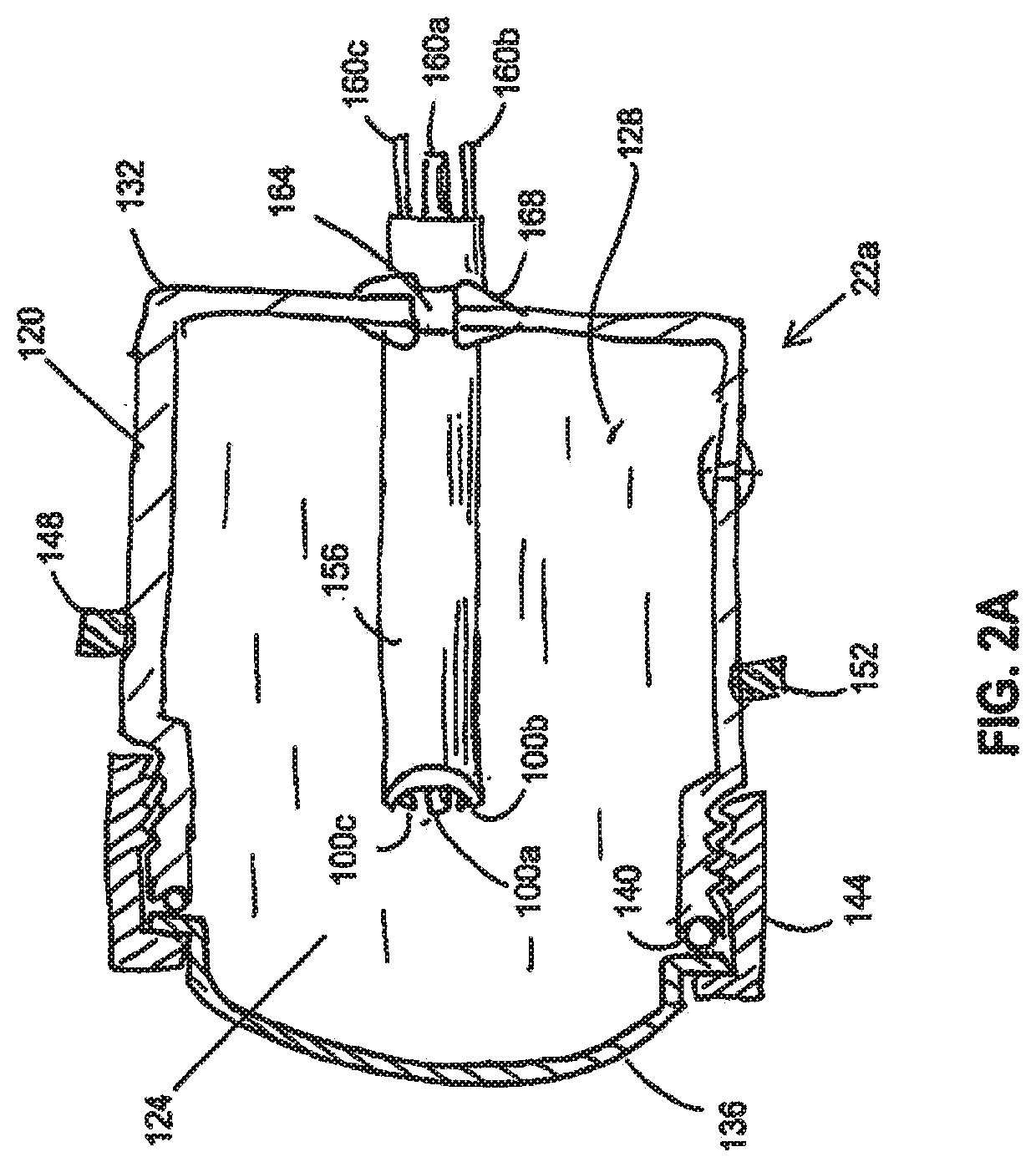
[0097]FIG. 2A depicts an enlarged cross-sectional view of first embodiment of a removable spark head or module 22a. In the embodiment shown, spark head 22a comprises a sidewall 120 defining a spark chamber 124, and a plurality of electrodes 100a, 100b, 100c disposed in the spark chamber. In the embodiment shown, spark chamber 124 is filled with liquid 128 which may be similar to liquid 54 (FIG. 1). At least a portion of sidewall 120 comprises an acoustically permeable or transmissive material (e.g., a polymer such as polyethylene) configured to permit sound waves and / or shockwaves generated at the electrodes to travel through sidewall 120 and through chamber 18a. For example, in the embodiment shown, spark head 22a includes a cup-shaped member 132 that may be configured to be acoustically reflective and an acoustically permeable cap member 136. In this embodiment, cap member 136 is dome shaped to approximate the curved shape of an expanding wavefront that originates at the electrode...

second embodiment

[0099]FIG. 2B depicts an enlarged cutaway side view of a removable spark head or module 22b. In the embodiment shown, spark head or module 22b comprises a sidewall 120a defining a spark chamber 124a, and a plurality of electrodes 100d-1, 100d-2, 100, 100f disposed in the spark chamber. In the embodiment shown, spark chamber 124a is filled with liquid 128a which may be similar to liquid 128 and / or 54. At least a portion of sidewall 120a comprises an acoustically permeable or transmissive material (e.g., a polymer such as polyethylene) configured to permit sound waves and / or shockwaves generated at the electrodes to travel through sidewall 120a and through chamber 18a (FIG. 2). For example, in the embodiment shown, spark head 22b includes a cup-shaped member 132a that may be configured to be acoustically reflective and an acoustically permeable cap member 136a. In this embodiment, cap member 136a is dome shaped to approximate the curved shape of an expanding wavefront that originates ...

third embodiment

[0105]FIG. 2C depicts an enlarged cutaway side view of a removable spark head or module 22c. Spark head 22c is substantially similar to spark head 22b, except as noted below, and similar reference numerals are therefore used to designate structures of spark head 22c that are similar to corresponding structures of spark head 22b. The primary difference relative to spark head 22b is that spark head 22c includes a beam 172a that does not have a hinge, such that flexing of the beam itself provides the movement of electrodes 100d-1 and 100d-2 in the up and down directions indicated by arrows 180, as described above for spark head 22b. In this embodiment, the resonant frequency of spark head 22c is especially dependent on the physical properties (e.g., mass, stiffness, cross-sectional shape and area, length, and / or the like) of beam 172a. As described for spring arms 184 of spark head 22b, beam 172a is configured to be biased toward electrode 100e, as shown, such that electrode 100d-1 is ...


PUM


Abstract

Methods and systems for method for acoustic treatment of tissue to disperse vacuoles within the tissue. Some of the present methods and systems comprise: directing pulsed acoustic waves from the acoustic wave generator into the tissue containing the vacuoles. Some of the present methods include indentifying the location of tissue containing vacuoles, and/or coupling (e.g., acoustically) an acoustic wave generator to the tissue containing the vacuoles.

Description

CROSS-REFERENCE TO RELATED APPLICATIONS[0001]This application claims priority to U.S. Provisional Patent Application No. 62 / 312,372, filed Mar. 23, 2016, which is incorporated by reference in its entirety.BACKGROUND1. Field of the Invention[0002]Embodiments of the present invention relate generally to therapeutic uses of shock waves. More particularly, but not by way of limitation, embodiments of the present invention relate to an apparatus for generating therapeutic shock waves (shock waves with therapeutic uses) for use in a dermal clearing system and applications of same.2. Description of Related Art[0003]Shockwaves have been used in certain medical and aesthetic therapies. “Shock wave” or “shockwave” is generally used to refer to an acoustic phenomenon (e.g., resulting from an explosion or lightning) that creates a sudden and intense change in pressure. These intense pressure changes can produce strong waves of energy that can travel through elastic media such as air, water, hum...

Claims


Application Information

Patent Timeline
Patent Type & Authority Applications(United States)
IPC IPC(8): A61H23/00A61H23/02A61H23/04A61B18/20
CPCA61H2201/1207A61B2018/00458A61H2201/10A61B2018/00476A61B2017/00769A61H23/008A61H23/04A61B18/203A61H23/0245A61B2018/0047A61N7/00A61B17/225A61B2017/00756A61B2017/00761A61B2018/00452A61N2007/0034A61N7/02A61N2007/0056A61N2007/0069A61B2017/00154A61N5/0616A61B17/22004
Inventor CAPELLI, CHRISTOPHERROBERTSON, DAVID
Owner SOLITON
Why Eureka
Try Eureka