Aircraft flow body

a flow body and aircraft technology, applied in the field of aircraft flow bodies and aircraft, can solve the problems of plastic deformation, foreign object debris directly impacting the spar, tearing or being penetrated, etc., and achieve the effects of improving the distribution of impact load, flexible design, and stiffening the spar

Inactive Publication Date: 2020-07-02
AIRBUS OPERATIONS GMBH
View PDF0 Cites 0 Cited by
  • Summary
  • Abstract
  • Description
  • Claims
  • Application Information

AI Technical Summary

Benefits of technology

[0011]A rib with a first portion configured to enable an improved distribution of impact load between the rib and outer skin, coupled to a second rib portion that may provide a separate structural function, e.g., provide a stiffening of the spar is advantageous as it results in a versatile design. Furthermore, in the event of an impact damage, the damaged first rib portion may be disconnected / decoupled from an undamaged second rib portion, which may be attached to an undamaged spar. This results in a design that is less costly to repair after an impact damage as only a portion of the rib may need replacement rather that the entire rib.
[0012]In another embodiment of the present invention, the aircraft flow body comprises a lap joint that is orientated substantially perpendicular to the direction of the impact load. A joint between the first and second rib portions configured as such may result impact loads being transferred more uniformly across the full height (measured in vertical direction) of the rib, which may be advantageous in that the likelihood of plastic deformation of the second rib portion and the spar may be further reduced.
[0013]In yet another embodiment of the present invention, the lap joint comprises a single row of shear fasteners. A joint between the first and second rib portions provided with shear fasteners configured to shear once the impact load reaches a predetermined load may be advantageous in that as soon as the fasteners fail, the reaction of the impact load will be isolated to the outer skin and first rib portions, which may deform even further to react the impact loads.
[0014]In yet further embodiment of the present invention, the first rib portion and second rib portion are formed from dissimilar materials. Forming the rib portions from dissimilar materials enables the rib portions to be refined for their specific structural function(s), which may reduce cost and weight of the flow body as a whole.

Problems solved by technology

Furthermore this reduces the likelihood of the outer skin rupturing (tearing or being penetrated) before the impact load is absorbed, which may otherwise result in some foreign object debris directly impacting the spar and plastically deforming it.

Method used


Image

  • Aircraft flow body
  • Aircraft flow body

Examples


Embodiment Construction

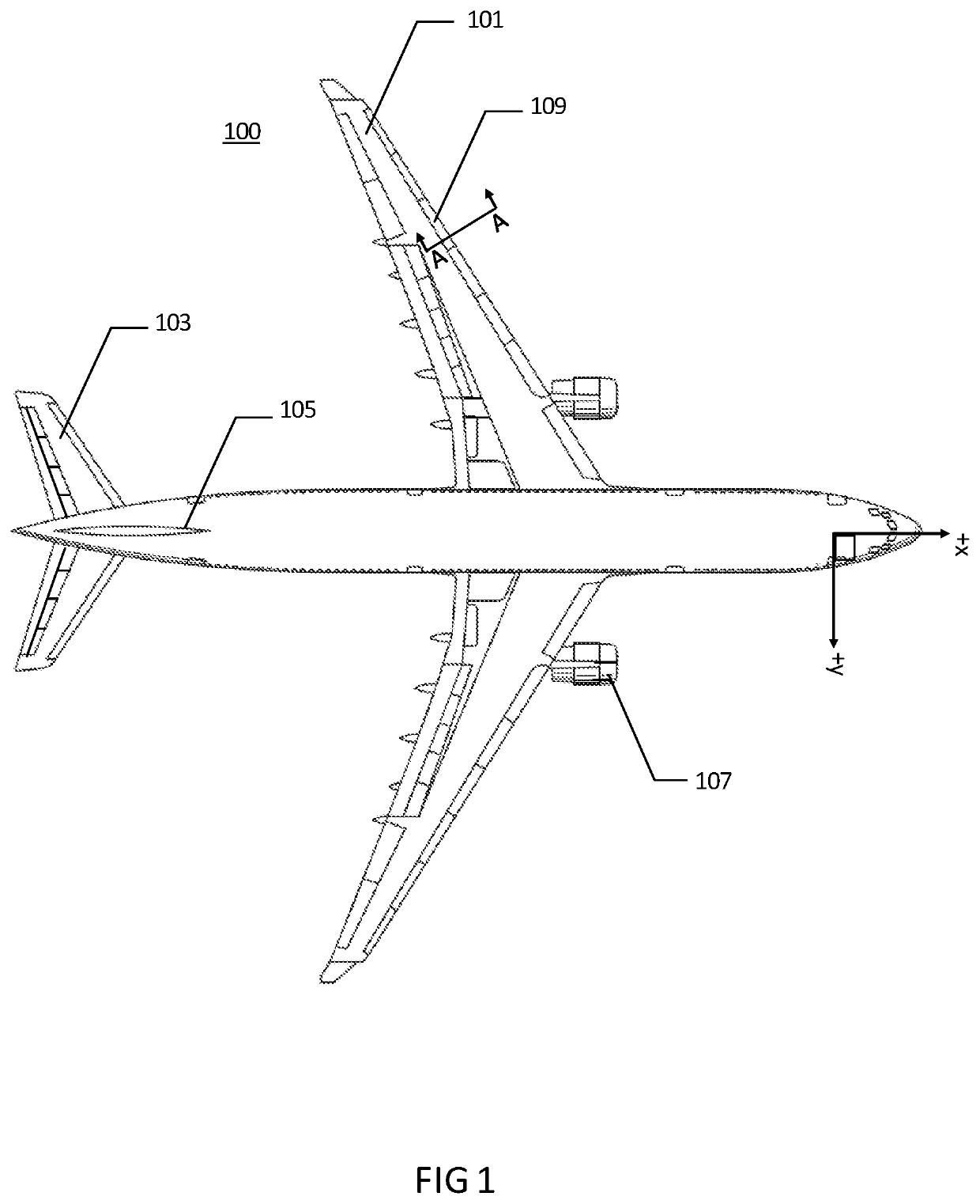
[0019]With reference to FIG. 1, an aircraft 100 is shown comprising a plurality of flow bodies such as the wing 101, horizontal tail 103, vertical tail 105, and engine nacelle 107. Each flow body comprises an internal structure comprising an outer skin attached to underlying spars and / or ribs and / or stiffeners. The aircraft comprises a set of orthogonal aircraft axes, comprising a longitudinal X axis, a lateral (spanwise) Y axis, and a vertical Z axis. The region of each flow body existing in the most positive X direction is commonly referred to as the leading edge region of the flow body and is most susceptible to impact from foreign objects travelling (relatively) in the −X direction. The wing 101 further comprises a plurality of smaller flow bodies in the form of slats 109, which are movably attached the forward (leading edge) region of the wing 101. These are constructed in substantially the same way as the larger structures in that they comprise an outer skin attached to underl...


PUM


Abstract

An aircraft flow body comprising a rib bounded by and fixedly attached to an outer skin, wherein the outer skin and the rib are configured to plastically deform when the outer skin is subjected to an impact load in a leading edge region of the airflow body, wherein the stiffness of the outer skin is greater than or equal to the stiffness of the rib when deformed by the impact load.

Description

CROSS-REFERENCES TO RELATED APPLICATIONS[0001]This application claims the benefit of the Great Britain patent application No. 1821332.2 filed on Dec. 31, 2018, the entire disclosures of which are incorporated herein by way of reference.FIELD OF THE INVENTION[0002]The present invention relates to an aircraft flow body and an aircraft comprising an aircraft flow body.BACKGROUND OF THE INVENTION[0003]The impact of one or more foreign bodies such as birds is a consideration during the design of aircraft flow bodies (wings, tails, nacelles etc.), which may be impacted by these bodies during their operational lifetime. It is a necessary consideration due to high impact energy that is imparted by the foreign object. The flow body structure needs to be damage tolerant and not fail to such an extent that it detaches from the aircraft. If the flow body also contains a liquid or gas tank, then the flow body should not suffer from a breach of containment.[0004]Typically these criteria are satis...

Claims


Application Information

Patent Timeline
Patent Type & Authority Applications(United States)
IPC IPC(8): B64C3/26B64C1/12
CPCB64C3/26B29L2031/3085B64D2045/0095B64C2001/0072B64C2201/021B64C3/187B64C1/12B64D45/00B64C3/28B64C3/18B64C5/00B64C9/22Y02T50/40B64U10/25
Inventor BENSMANN, STEFAN
Owner AIRBUS OPERATIONS GMBH
Why Eureka
Try Eureka