Coating Weight Control Apparatus and Coating Weight Control Method

a control apparatus and coating technology, applied in the direction of coating, coating, metal material coating process, etc., can solve the problems of high cost of the system of interest, high cost, and difficulty in detecting the strip passing position with high accuracy, so as to prevent the imbalance of coating weight, reduce risk, and change the tension

Active Publication Date: 2020-07-02
HITACHI LTD +1
View PDF0 Cites 5 Cited by
  • Summary
  • Abstract
  • Description
  • Claims
  • Application Information

AI Technical Summary

Benefits of technology

[0010]When the technique of Patent Document 1 is used, however, it becomes necessary to install a sensor for detecting a strip passing position. This makes cost of a system of interest higher and also requires additional maintenance or calibration operation of the sensor. Also, accuracy of a coating weight in coating can be reduced, because the sensor for detecting a strip passing position is typically disposed in an upper portion of the nozzle, and the strip passing position detected by the sensor may not be exactly the same as an actual strip passing position of the nozzle. Further, detection of a strip passing position in a coating plant has a highly technological difficulty because of vibration or warp in a width direction of the strip, which makes it difficult to detect the strip passing position with high accuracy.
[0012]The technique of Patent Document 3 requires a large-scale equipment for restraining a strip, which increases cost of a system of interest.
[0013]In light of the problems described above, the present invention has been made in an attempt to, when a position of a nozzle is automatically controlled: estimate a movement amount of a strip passing position without using a special sensor for detecting the strip passing position; and to control the nozzle position based on the estimated result. This can also prevent imbalanced coating weights between a front and a back sides of the strip, resulting in a highly accurate control of the coating weights, and also prevent the nozzle and the strip from coming into contact with each other, which results in a continued safe control.
[0015]A strip passing position is moved when any of the following factors occurs: a welding point passing; a change in tension; and an operation of a correcting roll position. In the present invention, in response to the occurrence, a strip passing position movement amount estimate part is activated and calculates a movement amount of a strip passing position corresponding to any of the factors. A nozzle position control part shifts each of a front and a back side nozzle positions, based on the movement amount of a strip passing position. A relative distance between a nozzle and a strip can be thus kept constant. This makes it possible to prevent imbalanced coating weights on a front and a back sides of the strip caused by the strip passing position movement. This also makes it possible to reduce a risk that, when the strip comes close to either the front or the back side nozzle, the nozzle and the strip disadvantageously come into contact.
[0016]Further, in the present invention, a safe distance without the contact risk between the nozzle and the strip is inputted as an allowable nozzle gap. Control of a nozzle position is provided in a range in which the nozzle and the strip do not come in contact with each other, using the allowable nozzle gap. This makes it possible to eliminate a risk of the contact between the nozzle and the strip, which results in a continued safe control.

Problems solved by technology

This makes cost of a system of interest higher and also requires additional maintenance or calibration operation of the sensor.
Further, detection of a strip passing position in a coating plant has a highly technological difficulty because of vibration or warp in a width direction of the strip, which makes it difficult to detect the strip passing position with high accuracy.
Without taking the influence of the state quantities into consideration, Patent Document 2 may have such a problem that accuracy in estimating a strip passing position is reduced.
The technique of Patent Document 3 requires a large-scale equipment for restraining a strip, which increases cost of a system of interest.

Method used


Image

  • Coating Weight Control Apparatus and Coating Weight Control Method
  • Coating Weight Control Apparatus and Coating Weight Control Method
  • Coating Weight Control Apparatus and Coating Weight Control Method

Examples


first embodiment

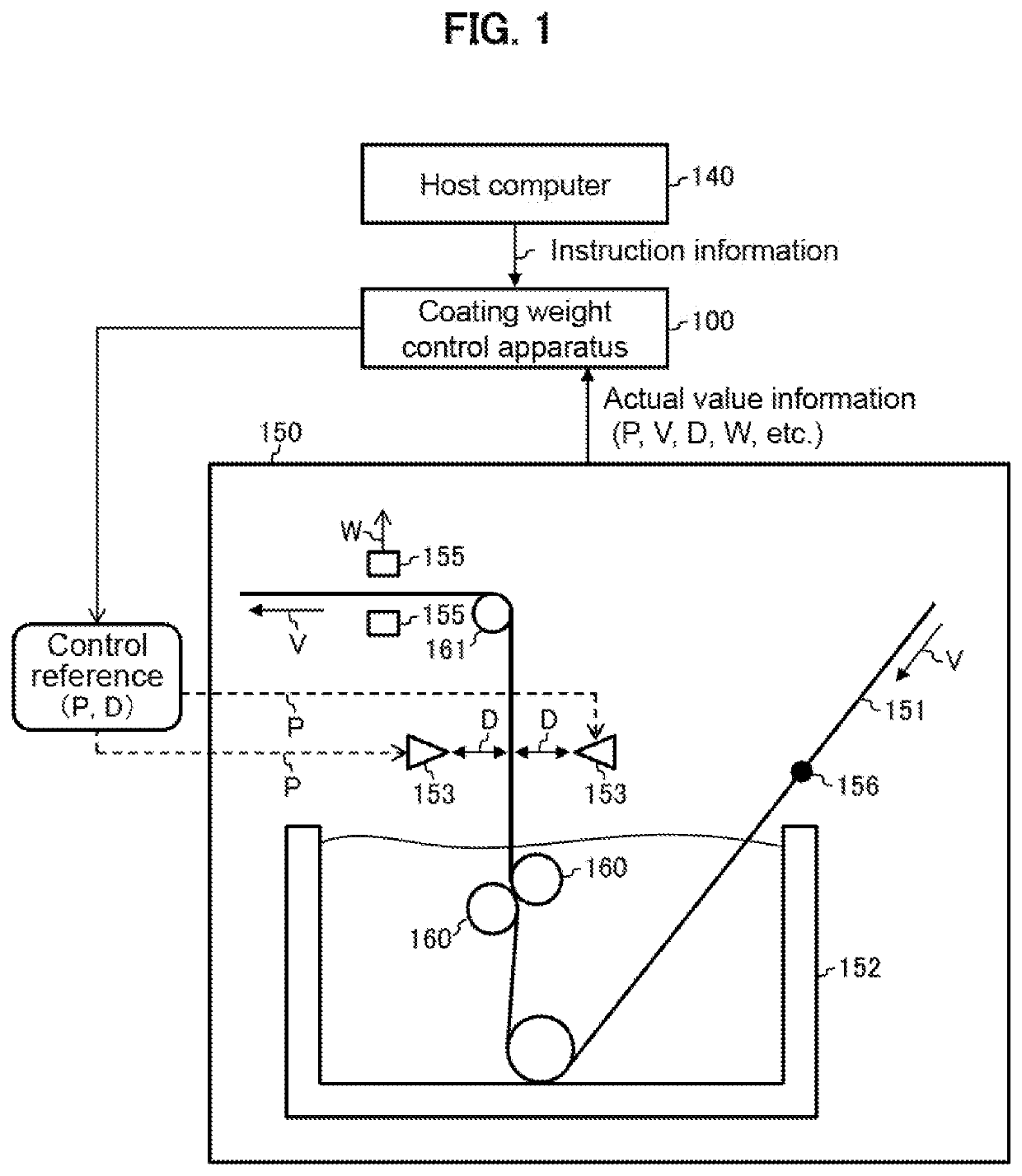
[0032]FIG. 1 is an explanatory diagram illustrating a coating plant according to an embodiment of the present invention. A coating weight control apparatus 100 (see FIG. 12 for details) controls a coating plant 150, and a strip 151 is thereby coated with a hot-dip bath in a desired thickness.

[0033]The coating plant 150 is described below. A pot (bath) 152 of the coating plant 150 is filled with a hot-dip bath, into which a series of strips 151 in which adjacent strips are welded at a welding point 156 are fed one after another. The strip 151 supported by a correcting roll 160 composed of two rolls and is controlled so as to have a constant tension value between the correcting roll 160 and a top roll 161. When one strip 151 currently being treated is fed and another to be treated next follows across the welding point 156, tension is changed, that is, tension before the welding point 156 is that of the currently-treated strip 151, and, after, that of the next strip 151.

[0034]The strip...

second embodiment

[0087]FIG. 9 is a block diagram illustrating a configuration of a coating weight control apparatus 100 according to a second embodiment of the present invention. The coating weight control apparatus 100 includes an allowable nozzle gap input part 903 that allows a user to input an allowable nozzle gap which is a minimum allowable distance between the nozzle 153 and the strip 151. The allowable nozzle gap used herein takes such a value that the strip 151 and the nozzle 153 do not come in contact with each other, taking into account a thickness of the strip 151, and a shape, a warp, and an amplitude of fluttering of an end of the strip 151, or the like. Generally, the strip 151 is not well-shaped at and around the welding point 156. The allowable nozzle gap can be thus set to a value a little on a large side before passing of the welding point 156 and can be then restored to its original value after passing of the welding point 156. Or, the allowable nozzle gap may be determined so as...


PUM

PropertyMeasurementUnit
thicknessaaaaaaaaaa
speedaaaaaaaaaa
pressuresaaaaaaaaaa

Abstract

A coating weight control apparatus includes: a strip passing position movement amount estimate part configured to estimate an movement amount of a strip passing position, in response to any of activation factors for movement of a strip passing position, that is, a welding point passing, a change in tension, and an operation of a correcting roll; and a nozzle position control part configured to shift each of positions of a front side nozzle and a back side nozzle by an amount corresponding to the movement amount of the strip passing position estimated by the strip passing position movement amount estimate part.

Description

CROSS REFERENCE TO RELATED APPLICATION[0001]This application claims the benefit of Japanese Patent Application No. 2018-248025 filed on Dec. 28, 2018, the disclosure of which is incorporated herein by reference.BACKGROUND OF THE INVENTION1. Field of the Invention[0002]The present invention relates to a coating weight control apparatus and a coating weight control method, in each of which a hot-dip coating bath in a desired thickness is attached to a steel strip in a continuous coating plant of a steel line. The present invention is in particular directed to the coating weight control method in which, when a coating weight is controlled by automatically controlling not only a pressure of a nozzle but also a position thereof, coating weights on both a front and a back sides of a strip can be controlled to respective target values, and the control can be continued in safety by minimizing a risk that the nozzle and the strip come in contact with each other.2. Description of the Related ...

Claims


Application Information

Patent Timeline
Patent Type & Authority Applications(United States)
IPC IPC(8): C23C2/20C23C2/40
CPCC23C2/40C23C2/20C23C2/003B05C3/02
Inventor KAYAMA, MASAHIROKURIHARA, SHIGETOSHIIWAHIRO, TAKANORIMORISHITA, HISAOSOGA, KAZUHIKOHIRANO, YUTA
Owner HITACHI LTD
Why Eureka
Try Eureka