

Rough-in Assembly for Free-Standing Faucet
a free-standing faucet and assembly technology, applied in water installations, domestic plumbing, construction, etc., can solve the problems of wobbling free-standing faucets, and achieve the effects of reducing production costs, simple structure, and easy production
- Summary
- Abstract
- Description
- Claims
- Application Information
AI Technical Summary
Benefits of technology
Problems solved by technology
Method used
Image

Examples
Embodiment Construction
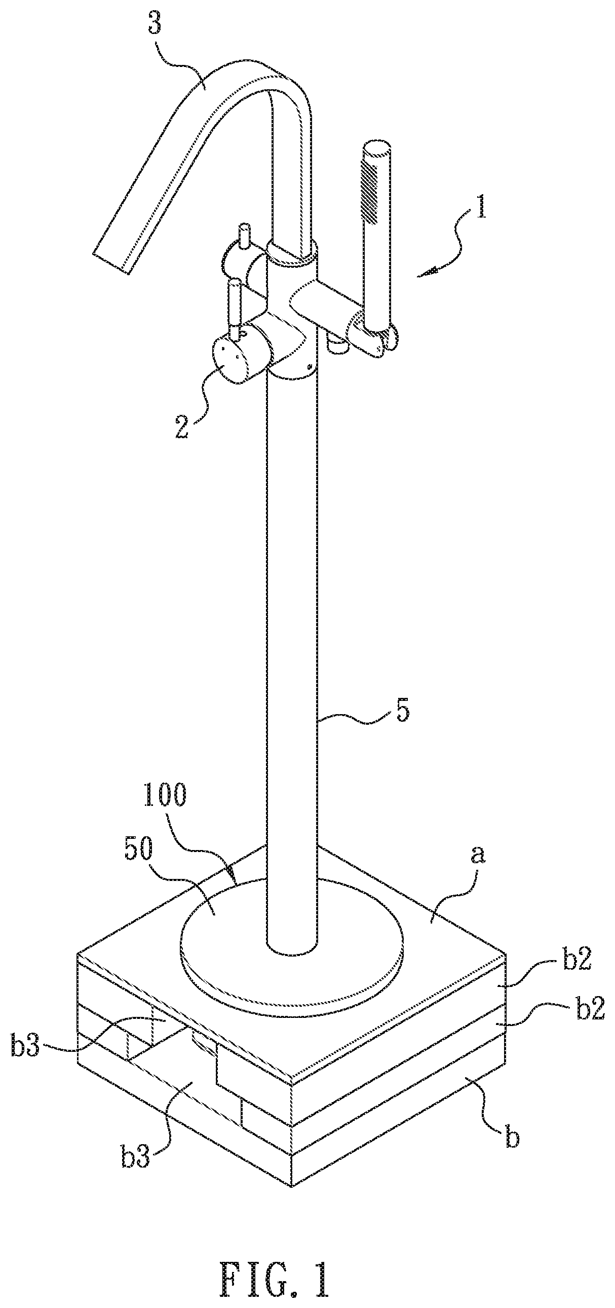
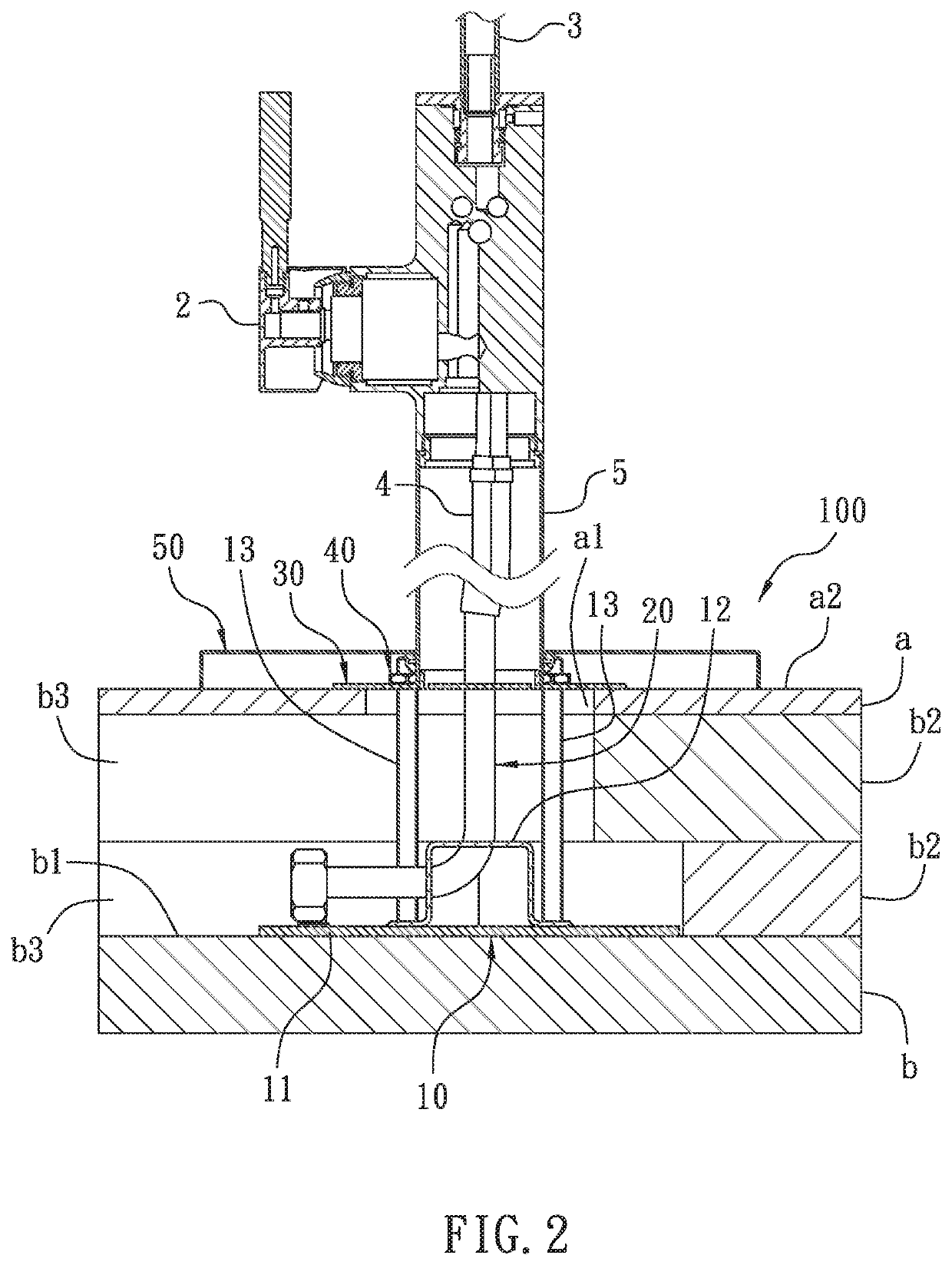
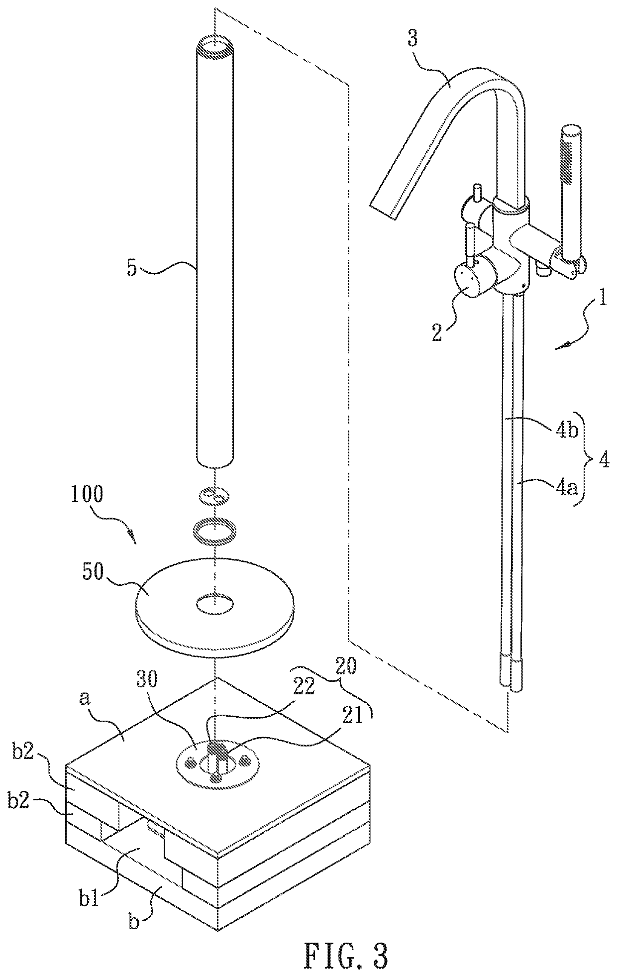
[0037]As shown in FIG. 1-4, an embodiment of a rough-in assembly 100 according to the present invention used for mounting a free-standing faucet 1 on a floor a, particularly the floor a around a tub is revealed. The floor a can be a tilt floor, a carpet floor, a wood floor, a laminate floor made from various materials, etc. The free-standing faucet 1 is basically separated from a tub and water flows into the tub through the free-standing faucet 1.
[0038]To be more precisely, the free-standing faucet 1 generally includes a valve assembly 2, a sprout 3 connected to the valve assembly 2, an inlet tube set 4 connected to the valve assembly 2, and a free-standing casing tube 5 connected to the valve assembly 2. The inlet tube set 4 is mounted in the free-standing casing tube 5 and is composed of a cold-water inlet tube 4a and a hot-water inlet tube 4b. As to the rough-in assembly 100, it consists of a mounting base 10, a connection tube set 2, a fixing plate 30 and a plurality of nuts 40....
PUM
 Abstract
Description
Claims
Application Information