Method for determining plane stresses on in-service steel structure member based on phase spectrum of ultrasonic transverse wave

a technology of ultrasonic transverse wave and plane stress, which is applied in the direction of force measurement, structural/machine measurement, instruments, etc., can solve the problems of difficult to ensure accuracy, constant external load on the infrastructure, and significant decrease in the safety status of the infrastructure, so as to achieve good applicability, easy to operate, and easy to ensure precision

Active Publication Date: 2020-07-09
HARBIN INST OF TECH SHENZHEN GRADUATE SCHOOL
View PDF0 Cites 9 Cited by
  • Summary
  • Abstract
  • Description
  • Claims
  • Application Information

AI Technical Summary

Benefits of technology

[0040](1) The method provided herein can realize the non-destructive determination for the plane stresses inside the steel structure members in construction and in service. Since the axial stress is a special case of the plane stress, the method through the simplification can also be applied to the determination of axial stress, and has a good applicability.
[0041](2) At present, when the plane stresses are determined by the ultrasonic method based on the acousto elasticity, the operation is complicated and the precision is difficult to ensure. While the method provided herein can overcome the deficiencies of the above method, and can quantitatively calculate the polarization angle by substituting the first response frequency and the derivative function maximum value of the phase difference into the corresponding formula in the case that the incident angle is measurable and known. In addition, the method of the disclosure is easy to operate and has high precision.
[0042](3) The method provided herein can be directly used to study the relationship between ultrasonic transverse wave echo and stresses by capturing the spectral characteristics in the frequency domain to establish a relationship with the plane stresses. In this method, the difference of echo signals is obvious in the frequency domain, allowing for a high sensitivity.
[0043]In summary, the method for determining plane stresses on an in-service steel structure member based on phase spectrum of ultrasonic transverse wave provided herein realizes the non-destructive determination of the plane stresses of the in-service steel structure member. This method does not involve high requirements for the sampling rate of the data acquisition system during the determination, and is less affected by the environmental high-frequency noise. Moreover, the instruments involved in this method are easy to install, low in cost and easy to operate. This method can be used for plane stress determination of steel structure member in construction and in service, and can also be applied to the determination of welding residual stress and loading stress of other metal components.

Problems solved by technology

However, the infrastructure is constantly subjected to external loads when it is used as a shelter for the human being.
In addition, long-term use may result in significant decrease in the safety status of the infrastructure, and the stress state has been considered as an important indicator to evaluate the safety performance of an in-service steel structure member.
However, since the wave velocity is not sensitive to changes in stress, there are many defects in the ultrasonic method for determining stress based on acousto elasticity, for example, the zero-stress state is required to be obtained; the time domain features are difficult to distinguish; and it is difficult to ensure the accuracy, greatly limiting its application and making it only effective in the relatively simple axial stress determination of an in-service steel structure member.
However, the actual engineering stress state is more complicated, and for most of the in-service steel structure members, the determination of the plane stresses is the key to understand the true stress state of the in-service steel structure member.

Method used


Image

  • Method for determining plane stresses on in-service steel structure member based on phase spectrum of ultrasonic transverse wave
  • Method for determining plane stresses on in-service steel structure member based on phase spectrum of ultrasonic transverse wave
  • Method for determining plane stresses on in-service steel structure member based on phase spectrum of ultrasonic transverse wave

Examples


example 1

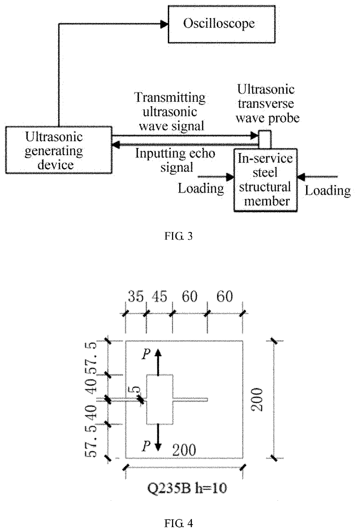
[0110]A steel plate A made of Q235B is used herein as the research object to construct the plane stress field. It can be found from the analysis about the factors affecting the axial stress that a smaller thickness will result in a larger amplification parameter of the determination error. However, the thickness of the research object cannot be limitlessly reduced to control the determination error. The thickness of the steel plate A is empirically selected to 1 cm. At the same time, the steel plate A is provided with a rectangular opening to avoid the field having a stress uniformity similar to the axial stress field. Then the steel plate A is loaded in a direction parallel to the plate by placing a hydraulic jack at the rectangular opening. The final plane stress field is schematically shown in FIG. 4, and the plane stress determining system is shown in FIG. 3. In order to ensure that the results are sufficiently reliable, a small test sample B with a size of 45.00 mm×30.00 mm×10....


PUM

PropertyMeasurementUnit
center frequencyaaaaaaaaaa
ultrasonicaaaaaaaaaa

Abstract

A method for determining plane stresses on an in-service steel structure member based on phase spectrum of ultrasonic transverse wave, including: calibrating stress-spectrum parameters k and c of a replica of the in-service steel structure member; determining a first response frequency of a phase difference and a maximum value of a derivative function of the phase difference of an ultrasonic transverse wave echo of the in-service steel structure member, and obtaining a polarization angle of ultrasonic transverse wave components generated by a birefringence effect; solving a plane normal stress difference and a plane shear stress inside the in-service steel structure member; and separating normal stresses by a shear difference method to obtain three independent plane stress components.

Description

CROSS-REFERENCE TO RELATED APPLICATIONS[0001]This application claims the benefit of priority from Chinese Patent Application No. 201910014154.9, filed on Jan. 8, 2019. The content of the aforementioned application, including any intervening amendments thereto, is incorporated herein by reference in its entirety.TECHNICAL FIELD[0002]The present disclosure relates to stress non-destructive determination of steel structure member, and more particularly to a method for determining plane stresses on an in-service steel structure member based on phase spectrum of ultrasonic transverse wave.BACKGROUND OF THE INVENTION[0003]With the development of economy, science and technology, a great progress has been made to the infrastructure construction, especially the construction steel structures. However, the infrastructure is constantly subjected to external loads when it is used as a shelter for the human being. These external loads include loads generated under normal use and loads caused by e...

Claims


Application Information

Patent Timeline
Patent Type & Authority Applications(United States)
IPC IPC(8): G01L1/25G01N29/04G01N29/07G01N29/12
CPCG01L1/255G01N29/043G01N29/07G01N2291/0234G01N29/12G01N2291/011G01N2291/0289G01M5/0041G01M5/0066G01N29/075G01N29/30G01N2291/02827G01N2291/101
Inventor LI, ZUOHUALIU, NANXILIU, DIANKUNWANG, YINGZHUTENG, JUN
Owner HARBIN INST OF TECH SHENZHEN GRADUATE SCHOOL
Why Eureka
Try Eureka