Battery Module, Battery Device, and Battery System Having Thermal Management Design

a battery module and battery technology, applied in the field of battery modules, battery devices, and battery systems having thermal management design, can solve the problems of etc., and achieve the effects of reducing the impact of environmental temperature, long service life of the battery device, and high energy and time efficiency

Active Publication Date: 2020-07-09
YUN ENERGY LTD CO
View PDF0 Cites 5 Cited by
  • Summary
  • Abstract
  • Description
  • Claims
  • Application Information

AI Technical Summary

Benefits of technology

[0016]An object of the present invention is to provide a battery module, battery device, and battery system having thermal management design, which can greatly reduce the impact of the environmental temperature to the battery device and battery system utilized in electric vehicle or other applications. Meanwhile, both quick thermal conditioning characteristic of the battery cells and battery modules in the battery device, and less temperature differences among the battery cells are available, resulting in high energy and time efficiencies, and long service life of the battery device. The battery module, according to the present invention, is defined as the one composed of a plurality of battery cells connected in parallel to form parallel set(s) with thermal management design, a plurality of parallel set(s) connected in series if necessary, and the associated circuits for voltage

Problems solved by technology

Meanwhile, both quick thermal conditioning characteristic of the battery cells and battery modules in the battery device, and less temperature

Method used


Image

  • Battery Module, Battery Device, and Battery System Having Thermal Management Design
  • Battery Module, Battery Device, and Battery System Having Thermal Management Design
  • Battery Module, Battery Device, and Battery System Having Thermal Management Design

Examples


first embodiment

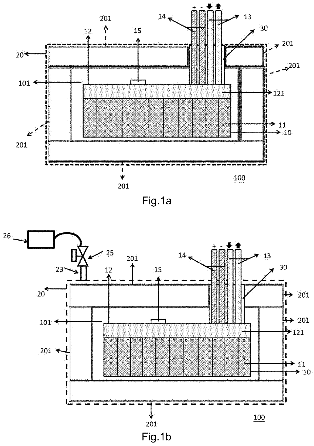
[0081]FIG. 1a is a perspective view of part of the battery system 100 and battery device having thermal management design (labelled as “10” and “20” in the figures) according to the present invention. It includes the battery device 10, formed by a plurality of the battery modules 11, the positive and negative terminals electrical cable wires 14, and the flow channel device 12; the system fluid pipe 13; and the enclosure 20 (as indicated by the dashed line), which has the sealing layer (201) for being a thermal insulation unit and the channel 30. The sealing layer (201) of the enclosure 20 is a confined space filled with gas, as indicated by the dotted arrow, for thermally insulating the battery device 10. The channel 30 communicates the space covered in the enclosure 20, which accommodates the battery module 11 and the flow channel device 12, with the outside of the enclosure 20. The system fluid pipe 13 and the positive and negative terminals electrical cable wires 14 are disposed ...

second embodiment

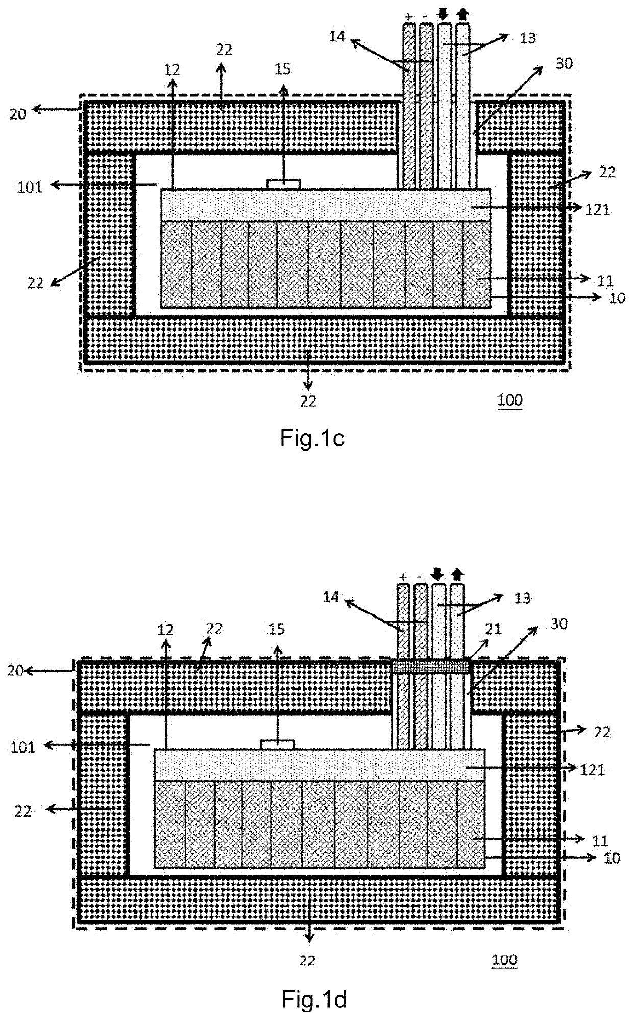
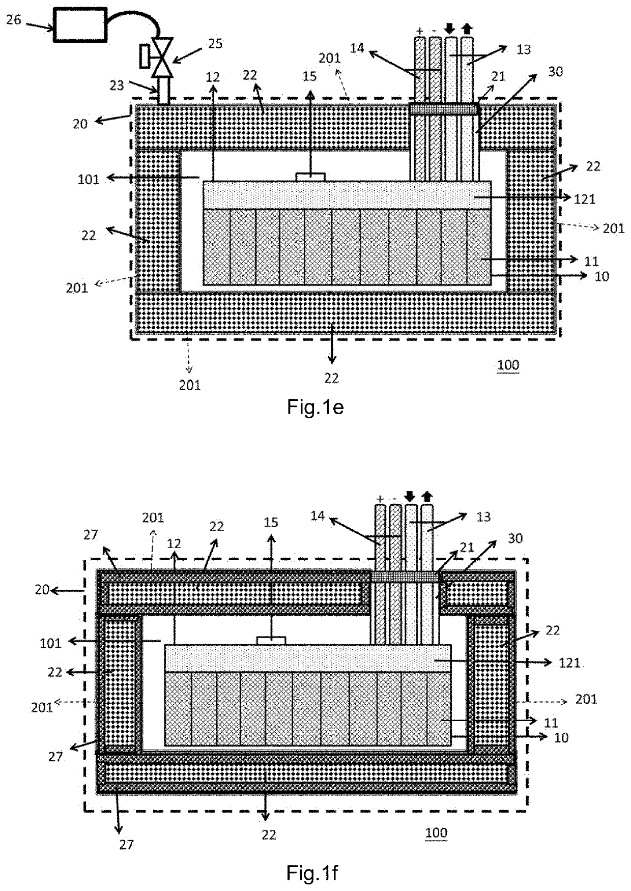
[0085]Referring to FIG. 1e, a battery device having thermal management design (including “10” and “20” in the figure) and part of a battery system 100 according to an alternative mode to the above second embodiment as FIG. 1d illustrated, wherein the enclosure 20 further comprises a seal perforation 23 arranged thereon, and the thermal insulation unit includes a sealing layer 201 filled by the first thermal insulation material 22 (as the scope indicated by the dotted arrow), wherein the sealing layer 201 is connected with the seal perforation 23. In other word, the first thermal insulation material 22 does not completely fill out the sealing layer 201, so it may regulate the air pressure of the residual space in the sealing layer 201 through the seal perforation 23. Also, the seal perforation 23 and the valve joint 25 are connected to a vacuum apparatus 26 in the manner mentioned above and in FIG. 1b, which would complete be repeated here.

[0086]Referring to FIG. 1e, a battery device...

fourth embodiment

[0100]FIG. 2f illustrated a battery device having thermal management design (10+20) and part of the battery system 100 according to an alternative mode to the above fourth embodiment illustrated in FIG. 2d, wherein the enclosure 20 can further has a second channel 32 arranged thereon, wherein the thermal insulation sealing layer 211 and the thermal insulation sealing layer 212 are respectively arranged on the first channel 31 and the second channel 32. The channel 31 is for arranging and disposing the system fluid pipe 13, while the second channel 32 is for arranging and disposing the positive and negative terminals electrical cable wires 14. Besides, the enclosure 20 can further has a seal perforation 23, a valve joint 25, and a vacuum apparatus 26 arranged thereon for regulating the vacuum pressure of the residual space left by the occupation thermal insulation material in the sealing layer 201 of the enclosure 20, so as to achieve a high thermal insulation result. The manner of a...


PUM


Abstract

The present invention provides a battery module, a battery device, and a battery system having a thermal management design. It utilizes a three-stage thermal management design of the battery module, the battery device, and the battery system to not only prevent the battery cells from being impacted by the environmental temperature, but also efficiently control the temperature of the battery cells, such that the battery cells can reach the requirements of temperature equalization and appropriate operating temperature. The thermal management design of the battery module is mainly a design of a battery cell charging and discharging circuit having heat exchange. The thermal management design of the battery device is mainly a battery device enclosure having a thermal insulation ability, so as to avoid or reduce the impact of the environmental temperature to the temperature of the battery module. The thermal management design of the battery system mainly comprises a temperature control medium circulation system which can enable the conditioned temperature control medium to exchange heat with the battery module by means of the battery device.

Description

NOTICE OF COPYRIGHT[0001]A portion of the disclosure of this patent document contains material which is subject to copyright protection. The copyright owner has no objection to any reproduction by anyone of the patent disclosure, as it appears in the United States Patent and Trademark Office patent files or records, but otherwise reserves all copyright rights whatsoever.BACKGROUND OF THE PRESENT INVENTIONField of Invention[0002]The present invention relates to a battery module, battery device, and battery system having thermal management design, and more particularly to a high efficient thermal management design for battery device and battery module, which is capable of significantly reduce the impact of environmental temperature to a battery device, so as to not only extend the service life of the battery cells, but also enhance the performance of the battery cells and the convenience to the user based on this overall thermal management design of the battery system.Description of R...

Claims


Application Information

Patent Timeline
IPC IPC(8): H01M10/6556H01M10/6552H01M10/44H01M10/658
CPCH01M10/6552H01M10/6556H01M10/658H01M10/443Y02E60/10H01M10/44H01M10/46H01M10/6553H01M50/204
Inventor CHENG, MING YAO
Owner YUN ENERGY LTD CO
Why Eureka
Try Eureka