Wing tilt actuation system for electric vertical take-off and landing (VTOL) aircraft

a technology of electric vertical take-off and landing and actuation system, which is applied in the direction of vertical landing/take-off aircraft, efficient propulsion technology, airflow influencers, etc., can solve the problems of increasing the weight and manufacture cost of helicopters, critical rotor design, and generally limited to relatively low flight speeds

Pending Publication Date: 2020-07-16
AMSL INNOVATIONS PTY LTD
View PDF5 Cites 8 Cited by
  • Summary
  • Abstract
  • Description
  • Claims
  • Application Information

AI Technical Summary

Benefits of technology

The present invention provides a vertical take-off and landing (VTOL) aircraft with electric rotors that can pivot between a vertical and horizontal position. The electric rotors are mounted on the wings and can generate thrust in different directions to achieve vertical and horizontal flight. The aircraft has a unique structure with a boxed wing or strut braced wing structure that allows for efficient use of space and reduces weight. The electric rotors are distributed along the wing and can be angled to generate different thrust lines. The invention also includes a control surface that can be pivoted between 80 and 100 degrees to achieve better performance and stability. The technical effects of the invention include improved efficiency, reduced weight, and improved performance and stability.

Problems solved by technology

There are several issues associated with helicopters which may be problematic in some applications, such as the high levels of noise output.
One such disadvantage associated with helicopters concerns the rotor design which is critical for flight.
This lack of redundancy dictates that large factors of safety must be applied to all components of the rotor and drive train, which adds considerably to the weight and manufacture cost of helicopters.
Whist drones are becoming commercially viable for delivering small payloads, they are generally limited to relatively low flight speeds, on account of the vertical axis of rotation of the rotors.
Furthermore, they tend to have reasonably low ranges of travel per battery charge.
There are several inherent disadvantages with existing tilt wing aircraft.
One disadvantage concerns the actuators and bearings or other such mechanisms required to control the angle of inclination of the wing between the take-off / landing configuration and the forward flight configuration.
However, in practice, the actuators and bearings add significant weight to the aircraft.
A disadvantage of the Lilium Jet™ type aircraft concerns the electric motors which are encased fan type motors.
This arrangement is highly energy intensive, resulting in reduced possible flight range for a given battery size.
Furthermore, the encased fans can only be operated for take-off and landing on hardstand surfaces, such as designated landing pads and runways.
This limits the usability of the aircraft, and prevents it from being operated during take-off and landing on non-hardstand surfaces, such as parks, fields and gardens.
For military applications, this is undesirable, and does not cater for impromptu landings in remote locations.
A disadvantage of this concept aircraft is that each electric motor is independently actuated, requiring a separate actuator for each motor.
As noted above, this requires significant additional weight for the actuation motor system.

Method used


Image

  • Wing tilt actuation system for electric vertical take-off and landing (VTOL) aircraft
  • Wing tilt actuation system for electric vertical take-off and landing (VTOL) aircraft
  • Wing tilt actuation system for electric vertical take-off and landing (VTOL) aircraft

Examples


Embodiment Construction

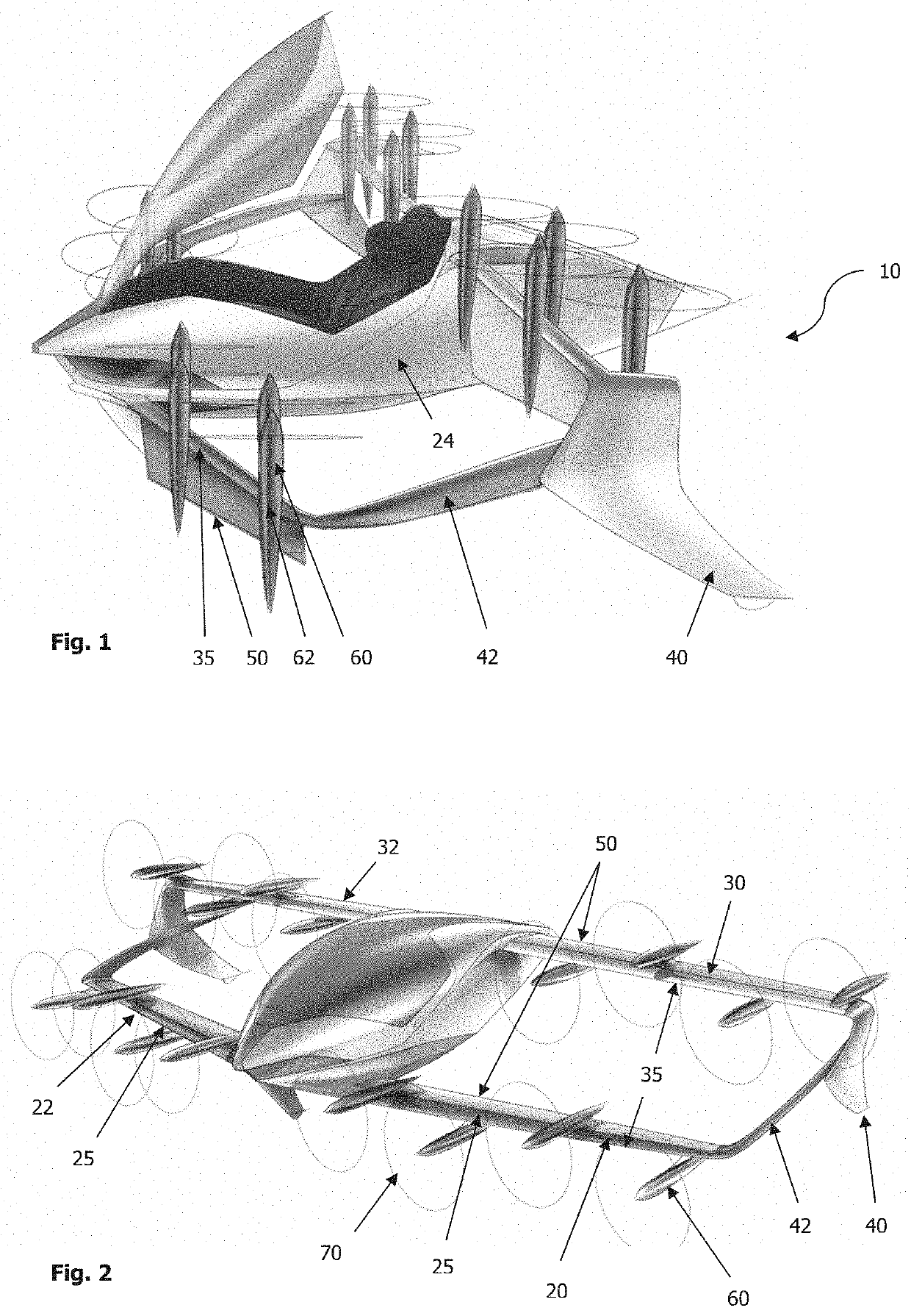
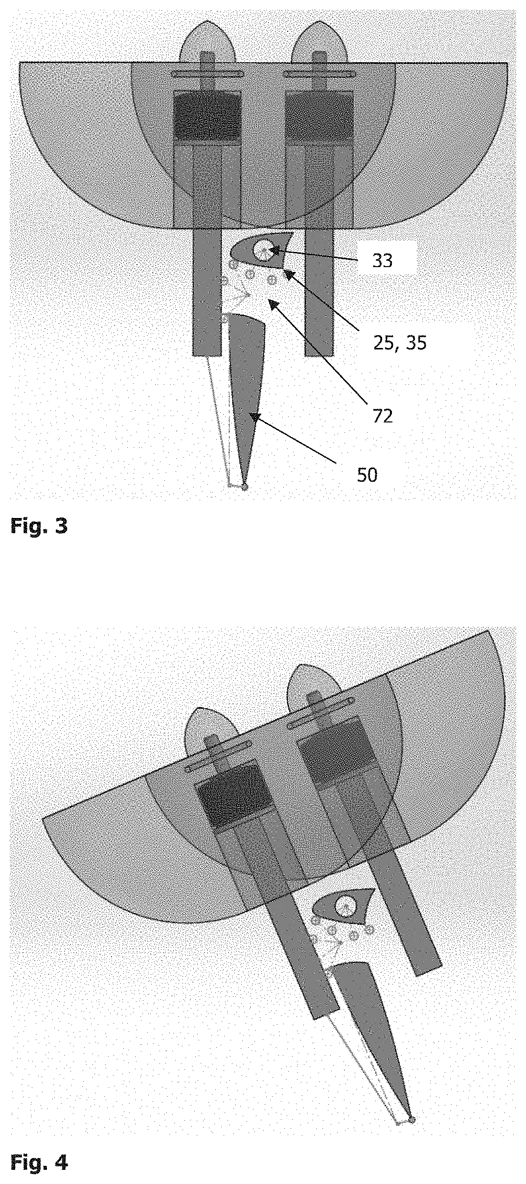
[0072]A vertical take-off and landing (VTOL) aircraft 10 is disclosed. In the preferred embodiment, as depicted in the drawings, there are two pairs of wings. Namely, the forward wings 20, 22 and the rearward wings 30, 32, Each of the forward wings 20, 22 is attached to a laterally opposing region of the fuselage 24. Similarly, each of the rearward wings 30, 32 is attached to a laterally opposing region of the fuselage 24. In the embodiment shown in the drawings, the aircraft 10 is depicted as a single seat or double seat aircraft 10. However, larger multi-person embodiments are also envisaged. The aircraft 10 may be controlled from within by a pilot, or alternatively it may be remotely controlled.

[0073]In the embodiment shown in the drawings, distal portions of the forward wings 20, 22 and the rearward wings 30, 32 are connected with connecting members or webs 42, such that the two pairs of wings 20, 22, 30, 32 define a boxed wing or closed wing structure.

[0074]In another embodimen...


PUM


Abstract

A vertical take-off and landing (VTOL) aircraft (10) comprises a fuselage (24) first and second forward wings (20, 22) and first and second rearward wings (30, 32), each wing having a fixed leading edge (25, 35) and a trailing control surface (50) which is pivotal about a generally horizontal axis. Electric rotors (60) are mounted to the wings (20, 22, 30, 32), the electric rotors (60) being pivotal with the trailing control surface (50) between a first position in which each rotor (60) has a generally vertical axis of rotation, and a second position in which each rotor (60) has a generally horizontal axis of rotation; wherein at least one of the wings (20, 22, 30, 32) has a first and a second electric rotor (60) which are each mounted having non-parallel axes of rotation so that the thrust lines of the first and second electric rotors are different.

Description

TECHNICAL FIELD[0001]The present disclosure relates to a wing tilt actuation system for electric vertical take-off and landing (VTOL) aircraft. In particular, the present invention relates to a wing tilt actuation system and mechanism for electric VTOL aircraft having passenger and / or military applications.BACKGROUND OF THE INVENTION[0002]VTOL aircraft are capable of take-off and landing vertically, or at some angle which is close to vertical. This style of aircraft includes helicopters and certain fixed wing aircraft, often used for military applications. Advantageously, VTOL aircraft permit take-off and landing in limited spaces, which negates the need for a large runway, and permits take-off and landing in small spaces and such as boat decks and landing pads on buildings and other structures.[0003]Helicopters are a style of aircraft in which lift and thrust are both provided by rotors. There are several issues associated with helicopters which may be problematic in some applicati...

Claims


Application Information

Patent Timeline
IPC IPC(8): B64C29/00B64C3/38B64C9/16B64C27/52B64C39/06B64D27/24B64C27/82
CPCB64C39/068B64C27/52B64C2027/8227B64C9/16B64C29/0033B64D27/24B64C27/82B64C3/38B64C39/024Y02T50/40Y02T10/72B64C9/18Y02T50/60B64D27/40B64C15/00B64C9/00B64C13/00B64C27/28B64C29/00B64C27/80B60L2200/10B64C1/1407B64C23/069B64C13/02Y02T50/10B60L15/20
Inventor MOORE, ANDREW DUDLEY
Owner AMSL INNOVATIONS PTY LTD
Why Eureka
Try Eureka