Inductive method and apparatus for battery storage

Pending Publication Date: 2020-07-16
REDPATH RICHARD +1
View PDF0 Cites 0 Cited by
  • Summary
  • Abstract
  • Description
  • Claims
  • Application Information

AI Technical Summary

Problems solved by technology

Although there are numerous portable light and light source modules for illumination, e.g. flashlights, the devices do not provide a utility and additional functionality for safe transport of their contained rechargeable lithium battery.
Lithium batteries

Method used


Image

  • Inductive method and apparatus for battery storage
  • Inductive method and apparatus for battery storage
  • Inductive method and apparatus for battery storage

Examples


Example

[0009]All illustrations of the drawings are for the purpose of describing selected versions of the present invention and are not intended to limit the scope of the present invention.

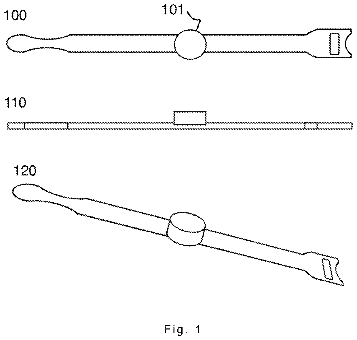
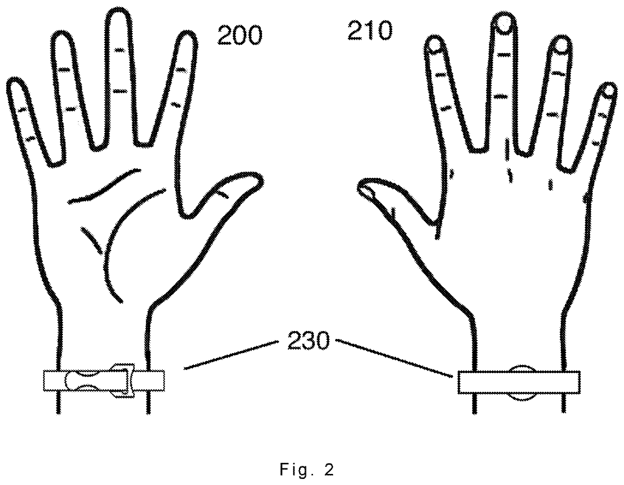
[0010]The invention is to use a magnetic field to an inductive switch to cut off power from the battery to the logic circuit of the device. Referring to FIG. 1 at 100, 110, and 120 are top, side and perspective views of a strap with a magnet at 101 attached. Referring to FIG. 2 at 200 and 210 is a bottom and top view of a hand with the strap in FIG. 1 at 100 worn by the hand at 200 and 210 views as shown in FIG. 2 at 230.

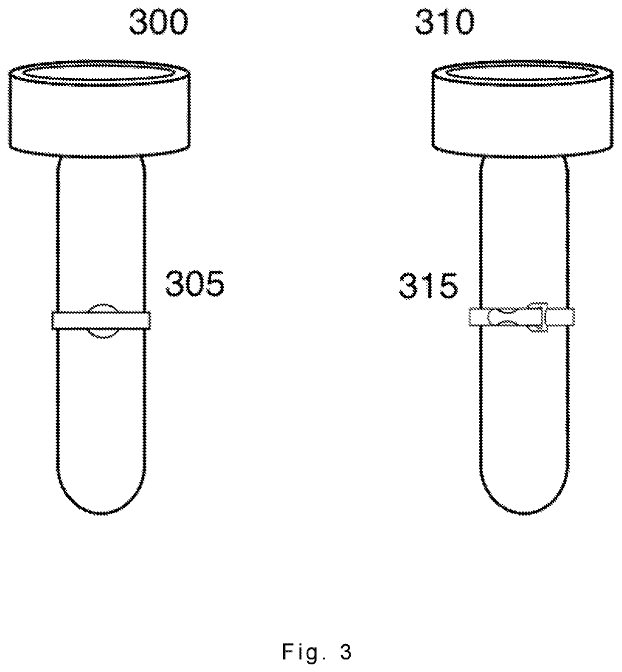
[0011]Referring to FIG. 3 at 300 and 310 is a top and bottom view of a flashlight. At 305 and 315 is a top and bottom view of the invention strapped onto the flashlight at 300 and 310 respectfully to use induction to switch off the battery connection.

[0012]Referring to FIG. 4 is a flowchart of the internal logic for a device such as a flashlight. At 410 is a battery power supply which is...


PUM


Abstract

The present invention relates to a method and apparatus for preventing the draining of power for an enclosed reusable battery system deployed for a rechargeable flashlight for shipping and storage.

Description

FIELD OF THE INVENTION[0001]The present invention relates to a battery-operated torch, e.g., flashlight, to secure safe for shipping and storage for intrinsic operation in an explosive environment. More specifically, the torch apparatus provides a magnetic inductive mechanism to cut off all power for shipping and long-term storage of rechargeable battery cells requiring special handling for dangerous goods transportation, especially in aircraft.BACKGROUND OF THE INVENTION[0002]Although there are numerous portable light and light source modules for illumination, e.g. flashlights, the devices do not provide a utility and additional functionality for safe transport of their contained rechargeable lithium battery. Lithium batteries are classified as dangerous goods and, as such, require special packaging for transportation. All domestic and international shipments containing lithium batteries are subject to transport regulations on hazardous goods according to ADR RID, ADN, IMDG, ICAO / I...

Claims


Application Information

Patent Timeline
IPC IPC(8): H02J7/00F21L4/00
CPCH02J2007/0067F21L4/005H02J7/0063
Inventor REDPATH, RICHARDREDPATH, JAMES
Owner REDPATH RICHARD
Why Eureka
Try Eureka