ENGINE SYSTEM AND OPERATING STRATEGY FOR SELECTIVE IN SITU AND EX SITU LIMITING OF NOx PRODUCTION

a technology of in situ and ex situ limiting and engine system, applied in the direction of electrical control, exhaust treatment electric control, separation process, etc., can solve the problems of large additional cost, complex overall system, and general need for active regeneration to achieve the effect of limiting nox output and reducing nox in the exhaus

Active Publication Date: 2020-07-23
CATERPILLAR INC
View PDF0 Cites 1 Cited by
  • Summary
  • Abstract
  • Description
  • Claims
  • Application Information

AI Technical Summary

Benefits of technology

[0005]In one aspect, a method of operating an engine system includes combusting a fuel and air compressed to an autoignition threshold in a plurality of combustion cylinders in an engine in the engine system, and limiting NOx production in situ during the combustion of the fuel and air. The method further includes filtering particulates in raw exhaust from the engine containing an engine-out NOx amount using a particulate filter coupled to the engine. The method still further includes conveying filtered exhaust containing the engine-out NOx amount from the particulate filter to a selective catalytic reduction (SCR) device, and producing, by the combustion of the fuel and air, heat energy of the filtered exhaust sufficient to warm the SCR device from a starting temperature to an activation temperature.
[0006]In another aspect, a method of operating an internal combustion engine system includes combusting fuel and air compressed to an autoignition threshold in a startup mode of an engine in the internal combustion engine system, and conveying exhaust produced by the engine in the startup mode through a non-catalyzed exhaust conduit to a bare particulate filter and a selective catalytic reduction (SCR) device positioned downstream of the bare particulate filter. The method further includes limiting NOx output of the internal combustion engine system in the startup mode at least in part by limiting NOx production in situ during the combustion of the fuel and air. The method still further includes combusting fuel and air compressed to an autoignition threshold in a running mode of the engine, and conveying exhaust produced by the engine in the running mode through the non-catalyzed exhaust conduit to the bare particulate filter and the SCR device, and limiting NOx output of the internal combustion engine system in the running mode at least in part by reducing NOx in the exhaust with the SCR device. The method still further includes transitioning the internal combustion engine system from the startup mode to the running mode based on warming of the SCR device to an activation temperature by heat energy of the exhaust produced by the engine in the startup mode.
[0007]In still another aspect, a compression ignition internal combustion engine system includes an engine including a cylinder block having a plurality of combustion cylinders formed therein, an intake manifold, and an exhaust manifold. The engine system further includes an exhaust system having an upstream exhaust conduit, a downstream exhaust conduit, and an exhaust placement mechanism structured to mix exhaust from the engine with fuel and air within the plurality of combustion cylinders. The upstream exhaust conduit has a raw exhaust inlet arranged to receive raw exhaust from the exhaust manifold, a raw exhaust outlet, and a diesel exhaust fluid (DEF) inlet positioned fluidly between the raw exhaust inlet and the raw exhaust outlet. The downstream exhaust conduit has a bare particulate filter having a filter inlet close-coupled to the raw exhaust outlet, a filter outlet, and a selective catalytic reduction (SCR) device having an SCR inlet close-coupled to the filter outlet, and an SCR outlet.

Problems solved by technology

Active regeneration generally requires additional equipment and undesired consumption of fuel energy.
Catalysts are often made of precious metals, and therefore require significant additional cost.
Other components such as selective catalytic reduction (SCR) devices to limit NOx are used in aftertreatment systems, and can make the overall system quite complex and expensive.
SCR devices have proven effective, however, there are certain operating windows, such as during cold start, where SCR devices are not sufficiently heated to begin working, and NOx is difficult or not possible to limit, at least without creating other challenges.

Method used


Image

  • ENGINE SYSTEM AND OPERATING STRATEGY FOR SELECTIVE IN SITU AND EX SITU LIMITING OF NOx PRODUCTION
  • ENGINE SYSTEM AND OPERATING STRATEGY FOR SELECTIVE IN SITU AND EX SITU LIMITING OF NOx PRODUCTION

Examples


Embodiment Construction

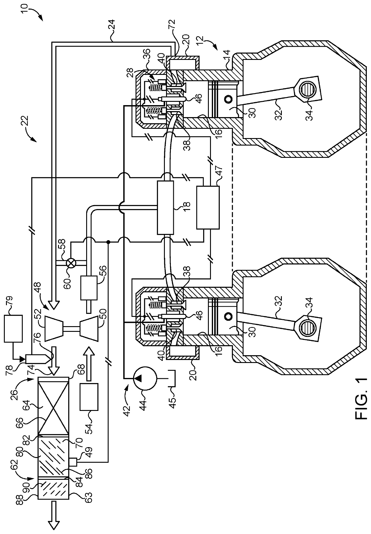
[0010]Referring to FIG. 1, there is shown a compression ignition internal combustion engine system 10, according to one embodiment. Internal combustion engine system 10 (hereinafter “engine system 10”) may operate on a liquid fuel, such as a diesel distillate liquid fuel, and includes an engine 12 having a cylinder block 14 with a plurality of combustion cylinders 16 formed therein. Engine 12 further includes an intake manifold 18 and an exhaust manifold 20. Combustion cylinders 16 may include any number, arranged in any suitable configuration. A plurality of pistons 30 are positioned one within each of combustion cylinders 16 and are movable, in a four-stroke engine cycle, between a bottom dead center position and a top dead center position to increase a pressure within a corresponding one of combustion cylinders 16 to an autoignition threshold. Each of pistons 30 is coupled with a connecting rod 32 that rotates a crankshaft 34, in a generally conventional manner. Engine 12 further...


PUM


Abstract

A compression ignition internal combustion engine system includes an engine and an exhaust system with an upstream exhaust conduit, a downstream exhaust conduit, and an exhaust placement mechanism for mixing exhaust with fuel and air within engine cylinders. The upstream exhaust conduit has a raw exhaust inlet, a raw exhaust outlet, and a diesel exhaust fluid (DEF) inlet between the raw exhaust inlet and the raw exhaust outlet. The downstream exhaust conduit includes a bare particulate filter and a selective catalytic reduction (SCR) device. Related methodology including operating the engine in a startup mode, and in a running mode once the SCR device is warmed, is also disclosed.

Description

TECHNICAL FIELD[0001]The present disclosure relates generally to an engine operating strategy for mitigating certain exhaust emissions, and more particularly to a multi-mode operating strategy for emissions reduction without the use of a diesel oxidation catalyst (DOC).BACKGROUND[0002]Reduction in certain emissions in exhaust from internal combustion engines has been of interest for many years. Combustion of a fuel and air within engine cylinders produces a variety of emissions, including water, carbon dioxide, particulate matter including soot and ash, unburned hydrocarbons, and oxides of nitrogen or “NOx.” Various regulations have been put in place over the years to limit output of certain emissions, notably particulate matter and NOx. Manufacturers of engines and related systems have devised a great many different strategies for limiting discharge of particulate matter and NOx to the environment.[0003]With regard to particulate matter, it has become conventional to equip internal...

Claims


Application Information

Patent Timeline
Patent Type & Authority Applications(United States)
IPC IPC(8): F01N3/20F01N3/035F01N3/08B01D53/94
CPCF01N3/0842F01N3/2066B01D53/9418F01N2610/02F01N3/035F01N2560/026F02D41/064F02D41/0077F02D41/0055F02D41/0255F01N3/2033F02D41/0245F02D41/029F01N13/009F01N3/208F01N2610/1453B01D53/9409B01D2257/404B01D2257/406B01D2258/012F01N3/021F01N9/00F02M26/05Y02T10/12Y02T10/40
Inventor ROBEL, WADE
Owner CATERPILLAR INC
Why Eureka
Try Eureka