Two-stage thermal oxidation of dryer offgas

a technology of thermal oxidation and dryer, which is applied in the direction of drying machines, lighting and heating apparatus, furnaces, etc., can solve the problems of not being able to achieve the required 1600° f. temperature of hot gas output of the thermal oxidizer, and not being able to achieve the optimal voc and co reduction

Active Publication Date: 2008-09-18
AEROGLIDE
View PDF1 Cites 36 Cited by
  • Summary
  • Abstract
  • Description
  • Claims
  • Application Information

AI Technical Summary

Benefits of technology

[0025]In the preferred process, the temperature of the dryer offgas emerging from the dryer is nominally in the range of 200-250° F. The temperature of non-preheated dryer offgas directed to the burner for NOx control is essentially the same. The temperature of the portion of dryer offgas recycled to the dryer is increased in the cold side of the primary heat exchanger by an amount of about 450-500° F., and preferably to a level of about 650-750° F. Similarly, the temperature of the preheated offgas...

Problems solved by technology

Heretofore, the temperature of the output from the thermal oxidizer has been limited to temperatures in the order of 1400° F. when the oxygen concentration is increased to 5% by volume; hence, VOC and CO reduction has not been optimum.
Even though residence time of the offgas being oxidized was not restricted and gas turbulence not a significant factor, it was not heretofore ...

Method used


Image

  • Two-stage thermal oxidation of dryer offgas
  • Two-stage thermal oxidation of dryer offgas
  • Two-stage thermal oxidation of dryer offgas

Examples


Embodiment Construction

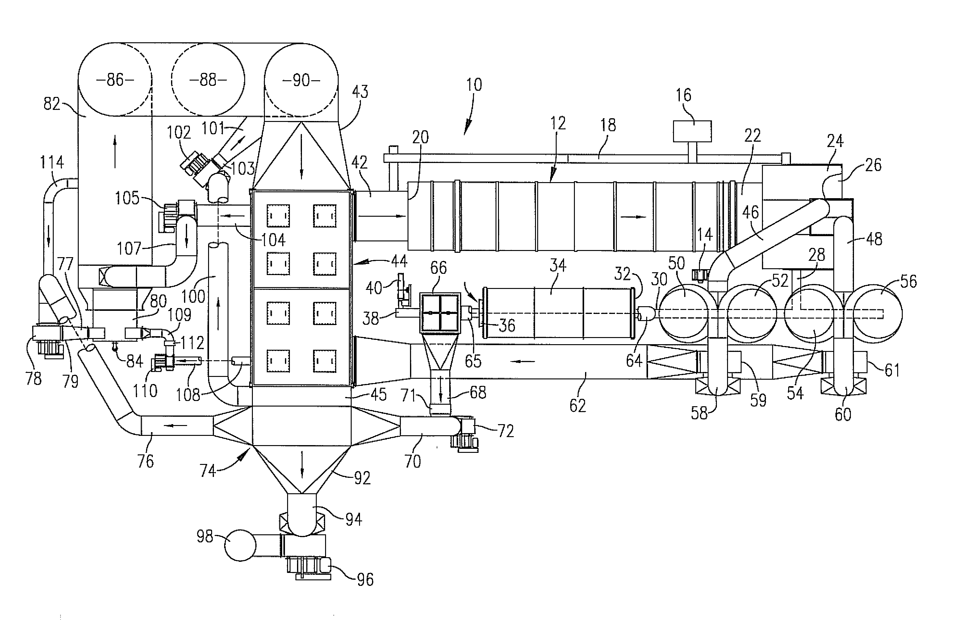
[0031]Apparatus for reducing the VOC and CO content of dryer offgas that is discharged into the atmosphere from a moist organic product drying process is shown schematically in FIG. 5 and designated by the numeral 10. The preferred moist product dryer 12 is a cylindrical, single-pass, co-current, three-stage, rotary drum, as illustrated, which is rotated about its longitudinal axis by a motor 14. Alternatively, the dryer may be of the rotary multiple-pass type. Further, the dryer may be of the non-rotating tubular type, or any type that incorporates direct-contact heat exchange between the product to be dried and a hot gaseous heat transfer media. Moist product to be dried is delivered from a schematically-shown source 16 to a conveyor 18 that directs product to the dryer product and gas inlet 20 of dryer 12. The dryer product and gas outlet 22 communicates with a centrifugal separator unit 24. A dropout chamber 26 is interposed between dryer product and gas outlet 22 and centrifuga...


PUM


Abstract

A method and apparatus are provided for reducing the VOC, CO, and, alternatively, the NOx content of dryer offgas that is discharged into the atmosphere from a moist organic product drying process using thermal oxidizing apparatus that includes a burner, furnace, mixing chamber, thermal oxidizer, tempering chamber, and an indirect gas-to-gas heat exchanger. The dryer offgas is separated into two portions, with a larger portion being preheated by indirect heat exchange with the hot gaseous output from the thermal oxidizer. The non-preheated portion is directed to the burner in the function of flue gas recycle for NOx control. The preheated portion is separated into two portions, with one portion being directed to the furnace/mixing chamber of the thermal oxidizing apparatus. The other portion of the preheated offgas is recycled to the hot gas inlet of the dryer and serves the function of dryer heat transfer media. Ultimately, all the dryer offgas enters the thermal oxidizer, and comprises a smaller non-preheated portion directed to the burner and a larger preheated portion directed to the furnace/mixing chamber. By preheating a large proportion of the offgas directed to the thermal oxidizing apparatus, simultaneous achievement of an adequate thermal oxidizer temperature, 1600° F., and an adequate oxygen concentration of 5% by volume is achieved for optimized thermal oxidation of carbon monoxide and volatile organic compounds.

Description

CROSS-REFERENCE TO RELATED APPLICATION[0001]The present non-provisional application claims the benefit of U.S. Provisional Patent Application No. 60 / 906,651, entitled TWO-STAGE THERMAL OXIDATION OF DRYER OFFGAS, filed Mar. 13, 2007, which is specifically incorporated herein by reference thereto.BACKGROUND OF THE INVENTION[0002]1. Field of the Invention[0003]This invention relates to a method and equipment for reducing contaminants such as volatile organic compounds (VOC's) and carbon monoxide (CO) normally present in dryer offgas that is discharged into the atmosphere from a moist organic product drying process. The equipment includes a product dryer, recuperative thermal oxidizing apparatus, a furnace having a burner, which serves to deliver hot products of combustion to the thermal oxidizing apparatus, and a gas-to-gas heat exchanger of the indirect type having a hot gas side and a cool gas side, hereinafter referred to as the primary heat exchanger, for bringing the hot gaseous o...

Claims


Application Information

Patent Timeline
IPC IPC(8): F26B3/02
CPCF26B23/022
Inventor RONNING, RICHARD L.WILSON, MICHAEL V.
Owner AEROGLIDE
Why Eureka
Try Eureka