Apparatus and method for mounting a flexible plate

a flexible plate and apparatus technology, applied in the direction of printing plates, printing presses, printing plates, etc., can solve the problems of reducing the speed and efficiency of mounting operation, reducing the accuracy of alignment between the printing plate and the printing cylinder, and reducing the accuracy of mounting operation, so as to improve the accuracy and repeatability of alignment, improve the alignment between the manipulator units, and improve the effect of accuracy

Active Publication Date: 2020-07-30
J M HEAFORD
View PDF0 Cites 0 Cited by
  • Summary
  • Abstract
  • Description
  • Claims
  • Application Information

AI Technical Summary

Benefits of technology

[0030]As described previously the flexible plate may be applied onto at least two support members, with the relief surface facing each support member. It has been found that improved accuracy when aligning the flexible plate with the sleeve or cylinder could be obtained by providing the flexible plate onto at least two support members having a curved profile, as opposed to providing the flexible plate on a single supporting surface such as a flat table.
[0031]Each support member may be mounted onto a manipulator unit, and the position of each manipulator unit may be independently adjusted axially to align the manipulator units with registration marks present on the arched flexible plate. Where appropriate, the position of each support member may also be independently adjusted in a radial direction. In this way, improved alignment between the manipulator units and the registration marks on the flexible plate can be obtained.
[0032]The alignment of each manipulator unit with the registration marks on the arched flexible plate may be carried out using an automated process. The automated process may be controlled by video recognition software or algorithms. This has been found to increase the accuracy and rep...

Problems solved by technology

This can lead to a reduction in the accuracy of alignment between the printing plate and the printing cylinder.
The operator may also experience difficulties in mounting the printing plate to the printing cylinder when the edges of the printing plate are curled, thereby reducing the speed and efficiency of the mounting operation.
A further disadvantage of conventional support tables is that they...

Method used


Image

  • Apparatus and method for mounting a flexible plate
  • Apparatus and method for mounting a flexible plate
  • Apparatus and method for mounting a flexible plate

Examples


Embodiment Construction

[0038]In order that the invention may be more clearly understood an embodiment thereof will now be described, by way of example only, with reference to the accompanying drawings, of which:

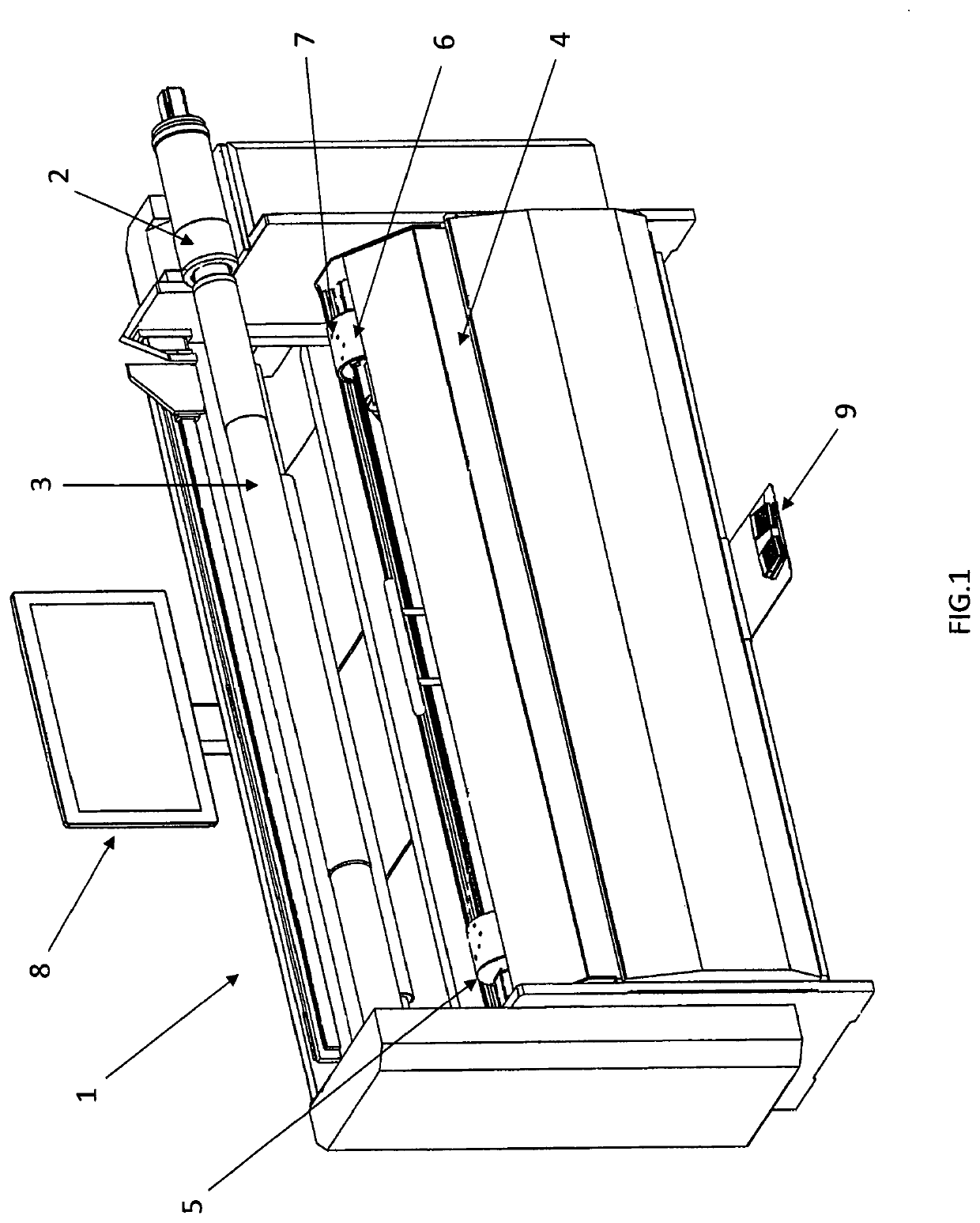
[0039]FIG. 1 shows a perspective view of a plate positioning and mounting apparatus according to the present invention.

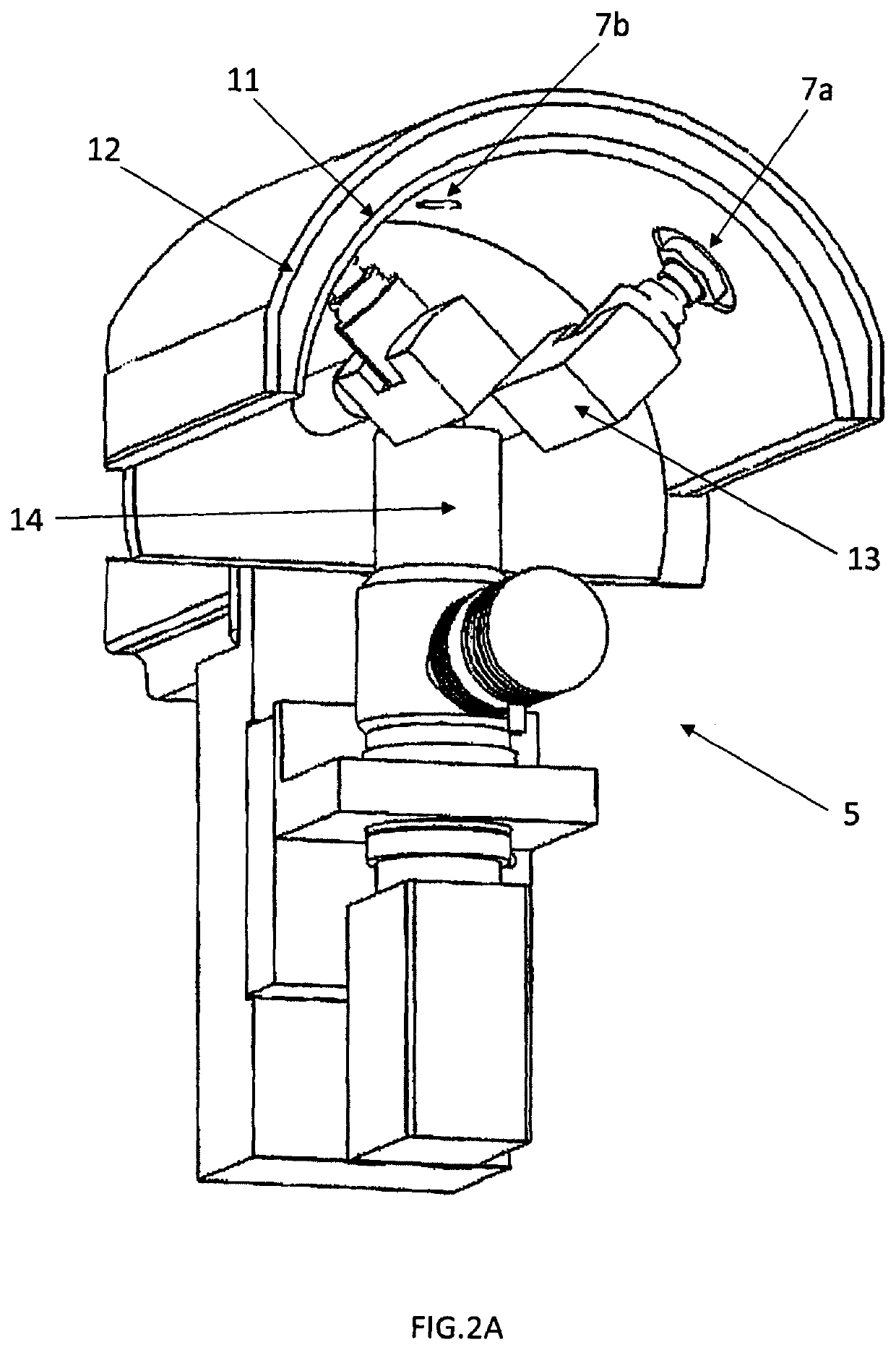
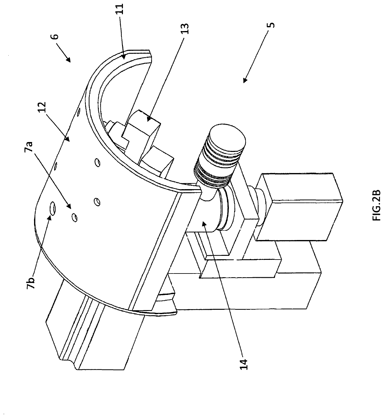
[0040]FIGS. 2A-B show perspective views of a manipulator unit according to the present invention.

[0041]FIG. 3 shows a perspective cut away view of the manipulator deck according to the present invention.

[0042]FIG. 4 shows a cross-sectional view of the manipulator deck in its lowered position.

[0043]FIG. 5 shows a cross-sectional view of the manipulator deck in its raised position.

[0044]FIGS. 6A-G show perspective views of the plate positioning and mounting apparatus in use when mounting a flexible plate onto a sleeve.

[0045]FIG. 7 shows a perspective view of the plate positioning and mounting apparatus with plate support wings.

[0046]FIG. 1 shows a plate positioning and mounting appar...


PUM


Abstract

The present invention relates to an apparatus for mounting a flexible plate onto a print sleeve or cylinder, wherein the apparatus comprises at least two manipulator units located below the print sleeve or cylinder and support members provided on each manipulator unit, wherein each support member has a curved profile for arching the flexible plate prior to its mounting onto the print sleeve or cylinder

Description

TECHNICAL FIELD OF THE INVENTION[0001]The present invention relates to an apparatus and to a method for mounting a flexible plate onto a print sleeve or cylinder.BACKGROUND TO THE INVENTION[0002]In the printing industry flexographic plates formed on one surface with a relief print have to be mounted with accuracy, either directly onto press cylinders (hereafter cylinder(s)) or onto cylindrical print sleeves (hereafter sleeve(s)) mounted on rotatable mandrels.[0003]The accuracy of mounting is particularly important when mounting photopolymer printing plates where the colours of an image (yellow, red, blue (cyan), black etc.) are overlaid to produce the finished image. Thus, the mounting operation has to be repeated with precision for each of the plates carrying the image portions for each colour, with four colours being typical. Registration marks, usually crosses or dots, are often provided on each printing plate to promote accurate alignment of the printing plates with the cylinder...

Claims


Application Information

Patent Timeline
IPC IPC(8): B41F27/00B41F27/12
CPCB41P2227/62B41F27/1206B41F27/005B41F27/14B41P2227/11B41F27/1275B41F27/06B41P2227/12B41P2227/30B41F27/1262B41F27/1287
Inventor LITTLER, GRAHAM
Owner J M HEAFORD
Why Eureka
Try Eureka