Powered, programmable machine and method for transforming a bicycle to fit particular riders and/or riding conditions

a technology of a programmable machine and a bicycle, applied in the direction of bicycle equipment, steering devices, transportation and packaging, etc., can solve the problems of increasing the risk of injury, poor fitting bicycles, and limiting the ability of a rider to efficiently transfer power to the drivetrain

Inactive Publication Date: 2020-07-30
ABBEY KENNETH ROBERT
View PDF0 Cites 4 Cited by
  • Summary
  • Abstract
  • Description
  • Claims
  • Application Information

AI Technical Summary

Benefits of technology

[0017]The present invention (“PowerFit”) provides a machine and method for transforming the fit of a bicycle “on-the-fly” using a central computer control device (“Control”) or another device such as a smartphone or cycling computer containing software or an app (“Control App”) permitting the device to function as a control device (“Control Device”). For simplicity, the Control or Control Device is referred to herein generically as the “Controller.” PowerFit consists of a Controller as well as separate actuator / sensor systems (“Actuators”) for each of the points of contact between the cyclist and the bicycle: saddle, handlebars, and pedals. It further provides a method for programming the Controller so that optimized fit settings (“Program Settings”) can be selected by the rider while riding to suit different riders and / or different conditions. Examples of such Program Settings might include, for example, “Ken's Fit” or “Dan's Fit”, “Climb,”“Descend,”“Sprint,” etc.

Problems solved by technology

Poorly fitting bicycles limit the ability of a rider to efficiently transfer power to the drivetrain, are uncomfortable, and increase the risk of injury due to accident or due to stress or repetitive motion.
Although modern bicycle fit technique and technology has become very sophisticated, it retains a number of significant limitations inherent to bicycle design: 1) it requires labor-intensive work to establish and maintain to optimum fit, 2) it does not permit a rider to safely or conveniently adjust fit while riding, 3) it ultimately achieves a compromise position that does not adjust for different riding conditions, for example climbing versus descending, 4) it does not permit rapid or convenient adjustment between different riders, for example when a racer needs to switch to a teammate's bicycle mid-race, 5) it cannot automatically adjust fit to different riders or conditions, 6) it cannot calculate a basic fit using computer algorithms, and automatically adjust the bicycle.

Method used


Image

  • Powered, programmable machine and method for transforming a bicycle to fit particular riders and/or riding conditions
  • Powered, programmable machine and method for transforming a bicycle to fit particular riders and/or riding conditions
  • Powered, programmable machine and method for transforming a bicycle to fit particular riders and/or riding conditions

Examples


Embodiment Construction

[0024]Selected embodiments will now be explained with reference to the drawings. It will be apparent to those skilled in the art from this disclosure that the following descriptions of the embodiments are provided for illustration only and not for the purpose of limiting the invention.

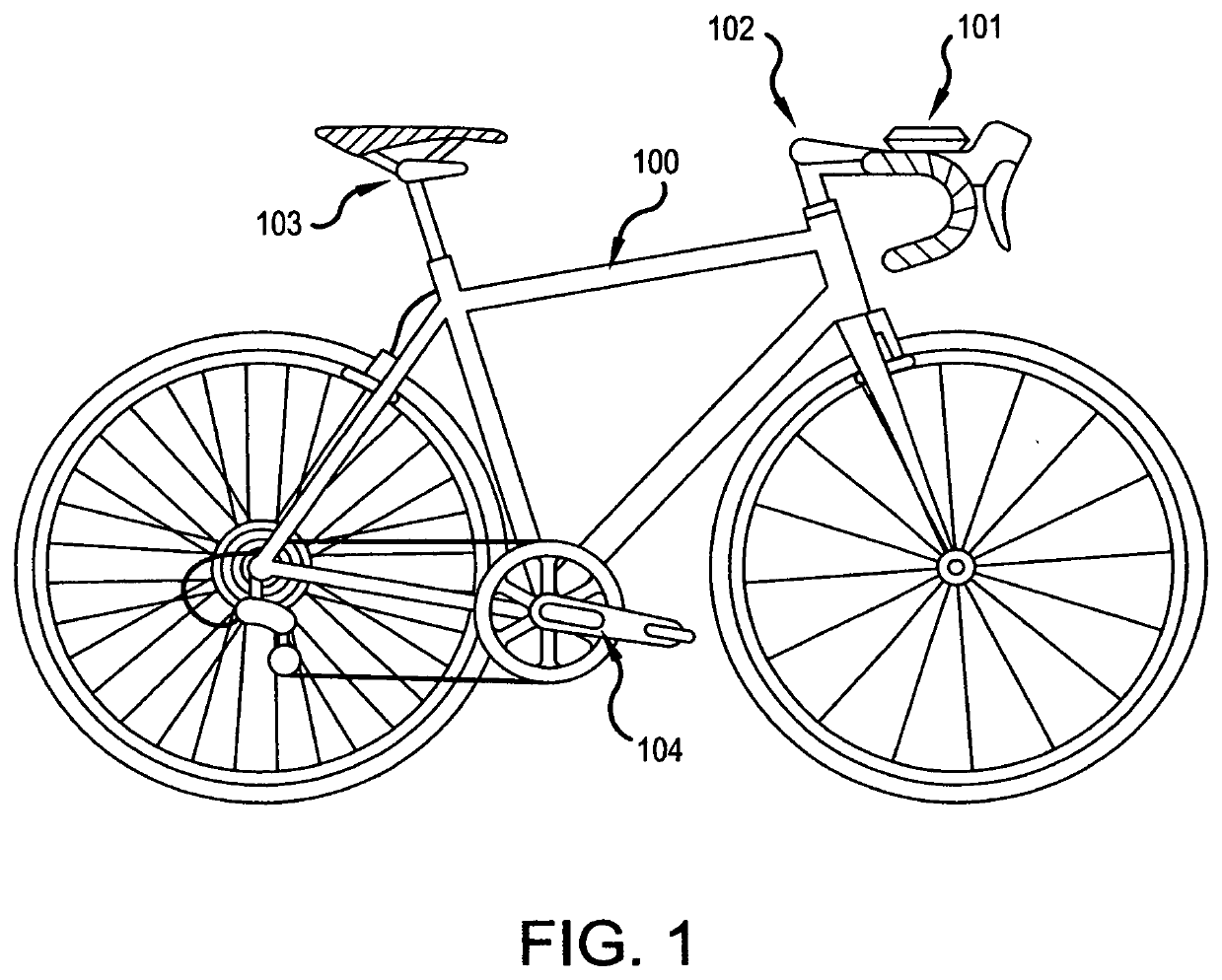
[0025]FIG. 1 demonstrates the general arrangement of the invention elements in one (preferred) embodiment as mounted on a representative road bicycle. The PowerFit elements are mounted on a bicycle 100 such that the Controller 101 is mounted on the right top bar of the handlebars. An Actuator to control the position of the handlebars (“Handlebar Actuator”102) is shown mounted to the top of the steerer tube. An Actuator to control the position of the saddle (“Saddle Actuator”103) is shown mounted under the saddle and attached to the seat post. An Actuator to control the length of the crank arm (“Crank Actuator”104) is shown mounted on the right crank arm. Another Crank Actuator (not shown) is mounted on...


PUM


Abstract

The present invention provides a means for powered, programmable transformation of a bicycle to fit a given cyclist for a given condition while riding. It comprises a computer/app and actuators to perform all adjustments while riding, that is programmable to recall fit information and/or to follow a fit algorithm that will transform a bicycle to match a particular rider's best fit for a particular condition such as climbing, descending, sprinting, etc. It also may adjust fit in response to “on-the-fly” rider commands, sensor inputs, and/or data from other devices.

Description

RELATED APPLICATIONS[0001]The present application is a utility patent application claiming the benefit of Provisional Patent Application No. 62 / 797,134, filed Jan. 25, 2019. The present application is based upon and claims priority from Application No. 62 / 797,134, the disclosure of which is hereby expressly incorporated herein by reference in its entirety.STATEMENT REGARDING FEDERALLY SPONSORED RESEARCH OR DEVELOPMENT[0002]Not Applicable.BACKGROUND OF THE INVENTIONField of the Invention[0003]The present invention relates to the fitting of bicycles for particular riders and particular conditions. It provides a computer-controlled machine and method for transforming the fit of the bicycle to suit a particular rider and / or condition and thereby optimize the rider's power output, speed, efficiency, and comfort. It also will provide for “on-the-fly” changes in position at the rider's discretion using a computer control device for rider-selected adjustment or by use of preprogrammed posit...

Claims


Application Information

Patent Timeline
Patent Type & Authority Applications(United States)
IPC IPC(8): B62M3/04B62M1/36B62K21/16B62J1/08B62J45/20B62J50/22B62K21/22B62J43/30B62J43/20B62J45/412B62J45/415H04W4/48
CPCB62M1/36B62K21/22B62M3/04B62J43/30B62J45/412B62J1/08B62J45/20B62K21/16B62J43/20B62J2001/085B62J50/22H04W4/48B62J45/415B62J1/10B62J45/4152B62M3/02H04L67/125H04L67/306
Inventor ABBEY, KENNETH ROBERT
Owner ABBEY KENNETH ROBERT
Why Eureka
Try Eureka