Medical image processing device

a technology of image processing and image, applied in image enhancement, instruments, applications, etc., can solve the problems of complexity and difficult to overlook, and achieve the effect of preventing overlooking of a lesion, facilitating setting and changing, and facilitating the effect of setting

Active Publication Date: 2020-07-30
FUJIFILM CORP
View PDF0 Cites 2 Cited by
  • Summary
  • Abstract
  • Description
  • Claims
  • Application Information

AI Technical Summary

Benefits of technology

[0016]According to the invention, it is possible to prevent overlooking of a lesion or the like by easily performing setting and changing of a notification method for notifying a user in a case where a region of interest as a target for diagnosis is detected from a medical image.

Problems solved by technology

However, as in JP2006-129950A and WO2015 / 011501A, in a case where a user is notified by a notice sound when an image is displayed according to a predetermined criterion, it is necessary to individually set selection items for a notification image for appropriate image diagnosis each time due to, for example, the difference in techniques used by the user to perform diagnosis using the images, or the difference in cases to be diagnosed, and thus there is a problem of complexity.
In this manner, the image may be easy to see and the lesion or the like may be difficult to overlook, but there is no description for a notification.

Method used


Image

  • Medical image processing device
  • Medical image processing device
  • Medical image processing device

Examples


first embodiment

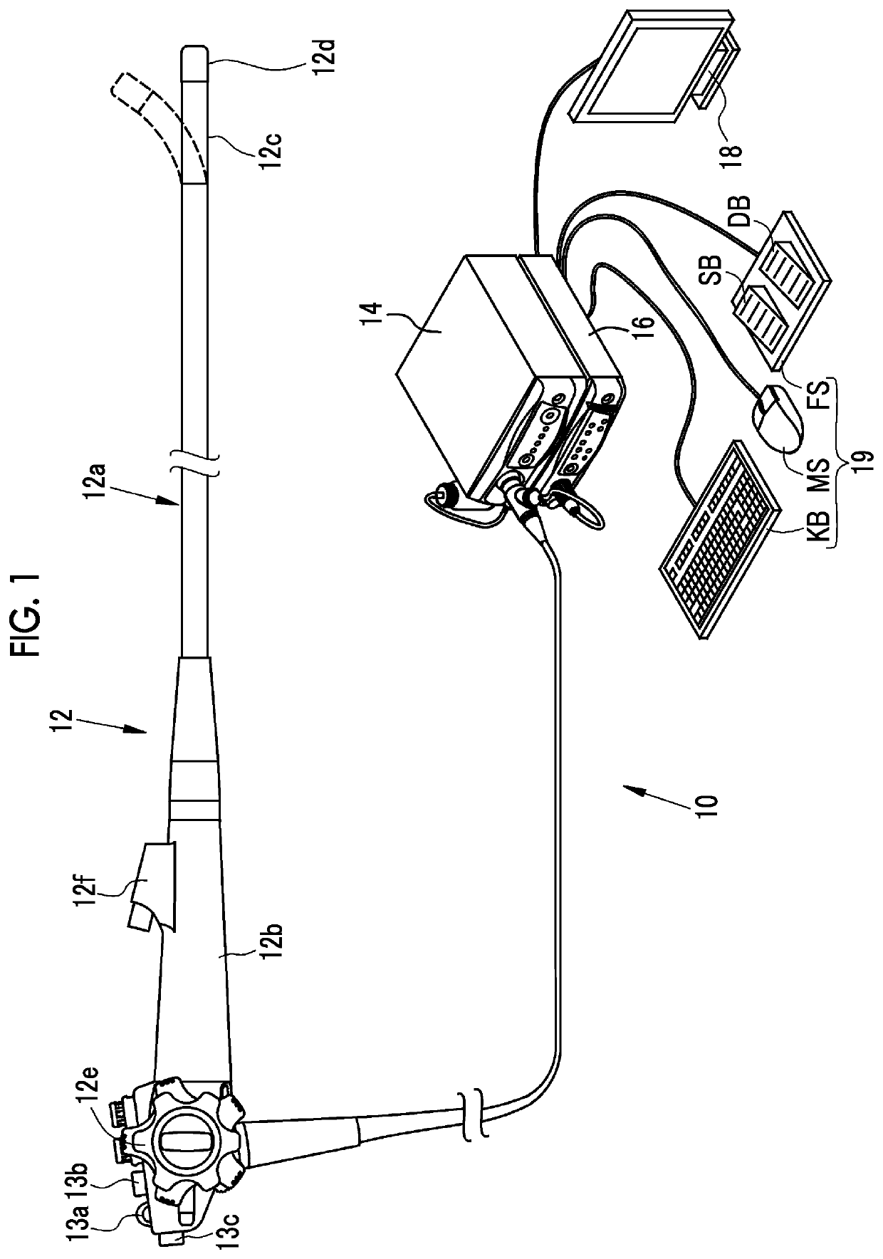
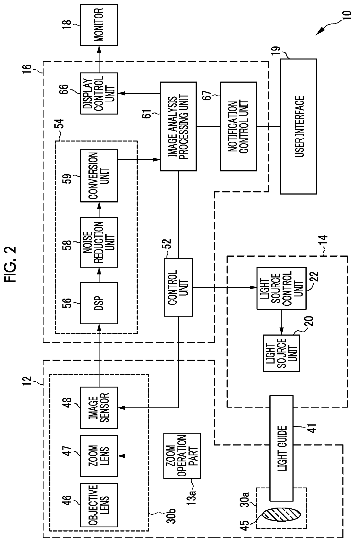
[0055]As illustrated in FIG. 1, an endoscope system 10 comprises an endoscope 12, a light source device 14, a processor device 16, a monitor 18, and a user interface 19. The endoscope 12 irradiates a subject as an observation target with illumination light, and images the subject irradiated with the illumination light. The light source device 14 generates illumination light to be emitted to the subject. The processor device 16 performs system control of the endoscope system 10, image processing, and the like. The monitor 18 is a display unit that displays an image output from the processor device 16. The user interface 19 is an input device, such as a keyboard, for performing a setting input or the like with respect to the processor device 16 and the like.

[0056]The endoscope 12 has an insertion part 12a that is to be inserted into an object to be examined, an operation part 12b provided in a proximal end portion of the insertion part 12a, and a bendable part 12c and a distal end par...

second embodiment

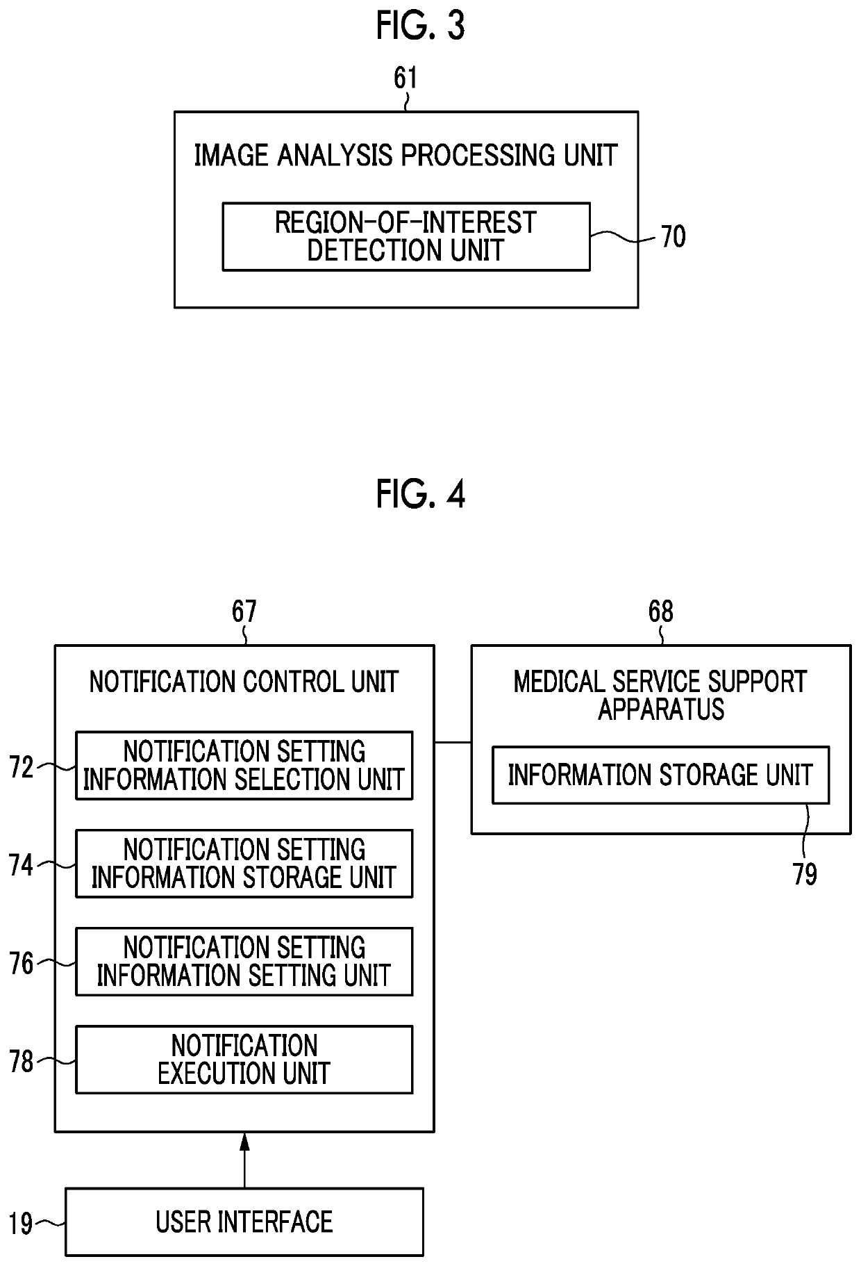
[0101]In the embodiment, notification setting information is selected using lesion information such as the size of a lesion, as the individual setting information. As illustrated in FIG. 22, the image analysis processing unit 61 includes a lesion determination unit 98 in addition to the region-of-interest detection unit 70. The lesion determination unit 98 determines lesion information indicating the content of a lesion for the region of interest detected by the region-of-interest detection unit 70. Different notifications are performed depending on the contents of the lesion on the basis of the determination result. In FIGS. 22 to 30, the devices and the like with the same reference numerals as in FIGS. 1 to 21 are the same as those described in the first embodiment, and thus the description thereof is omitted. In this example, similarly to the region-of-interest detection unit 70, also in the lesion determination unit 98, lesion information indicating the content of the lesion is ...


PUM


Abstract

A notification control unit includes a notification setting information selection unit, a notification setting information storage unit, a notification setting information setting unit, and the notification execution unit. Notification setting information is associated with individual setting information to be preserved in the notification setting information storage unit. The notification execution unit performs a notification according to setting of use-notification setting information which is selected by using the individual setting information by the notification setting information selection unit. The created or changed notification setting information is preserved in the notification setting information storage unit.

Description

CROSS-REFERENCE TO RELATED APPLICATIONS[0001]This application is a Continuation of PCT International Application No. PCT / JP2018 / 038061 filed on 12 Oct. 2018, which claims priority under 35 U.S.C. § 119(a) to Japanese Patent Application No. 2017-203863 filed on 20 Oct. 2017. The above application is hereby expressly incorporated by reference, in its entirety, into the present application.BACKGROUND OF THE INVENTION1. Field of the Invention[0002]The present invention relates to a medical image processing device in which setting and changing of a notification method at the time of notifying a user of a medical image are easy.2. Description of the Related Art[0003]In the current medical field, a medical image processing device using a medical image, such as an endoscope system comprising a light source device, an endoscope, and a processor device is widespread. In recent years, by performing image analysis on the medical image, a region of interest as a target for diagnosis is detected ...

Claims


Application Information

Patent Timeline
Patent Type & Authority Applications(United States)
IPC IPC(8): G06T7/00A61B1/00A61B1/06A61B1/04
CPCA61B1/06G06T7/0012G06T2207/30096G06T2200/24A61B1/00006A61B1/04A61B1/00055A61B1/0638A61B1/043A61B1/0646A61B1/00188A61B1/0004A61B1/00042A61B1/000094A61B1/0655
Inventor ENDO, MAIKO
Owner FUJIFILM CORP
Why Eureka
Try Eureka