Charging station, charging system and charging method for a drone

a charging system and charging method technology, applied in the field of drones, can solve the problems of increased affecting charge efficiency, flight safety concerns, etc., and achieve the effects of reducing the cost and human resource required for the use of repeatedly spraying conductive paint, increasing the impedance of charging plates, and reducing the use of conductive pain

Active Publication Date: 2020-07-30
CORETRONIC INTELLIGENT ROBOTICS CORP
View PDF0 Cites 4 Cited by
  • Summary
  • Abstract
  • Description
  • Claims
  • Application Information

AI Technical Summary

Benefits of technology

[0052]2. The light-absorbing layers are disposed on the top surfaces of the protecting covers, such that no conductive paint has to be additionally coated on the charging plates, such that cost and human resource required for the use of and repeatedly spraying the conductive paint can be saved.
[0053]3. After the charging stands of the drone are moved into the openings on the surface of the parking surface, the protecting covers are moved relative to the charging plates only after the drone is located on the charging position. Thus, the issue that the charging efficiency is degraded due to the increased impedance of the charging plates caused by the charging plates scratched by the charging stands during the centralizing and aligning process of the drone can be solved. In the words, in comparison with the related art, the invention can effectively maintain the charge efficiency of the charging plates.

Problems solved by technology

Thus, the charging plates reflect ambient light (e.g., the sunlight), which may cause the drone not to normally land due to misjudgment in the optical recognition when landing or extending the time required for landing, or even may cause flight safety concerns.
Such method may prevent a light reflection issue, but may cause increased impedance to the charging plates to affect charge efficiency, a coating method thereof is non-charging plating using a material having poor adherence, and re-spraying is required per month, which is time and labor consuming.
This method may cause the drone to fail to well utilize characteristics of 24-hour automatic execution of patrol tasks and may cause potential crisis to the drone due to the multiple positioning for landing.
However, this centralizing process usually leads to scratches to the charging plates by the charging stands of the drone, and after a long time, a gold plating layer is worn out to expose a copper layer.
As copper oxidation causes copper chloride, the charging impedance is increased, and charge efficiency is degraded, which results in a shortened lifespan of the charging plates or the need for regular maintenance.
Currently, such phenomenon is mitigated by increasing the thickness of the gold plating layer, which leads to the increase of maintenance cost.

Method used


Image

  • Charging station, charging system and charging method for a drone
  • Charging station, charging system and charging method for a drone
  • Charging station, charging system and charging method for a drone

Examples


Embodiment Construction

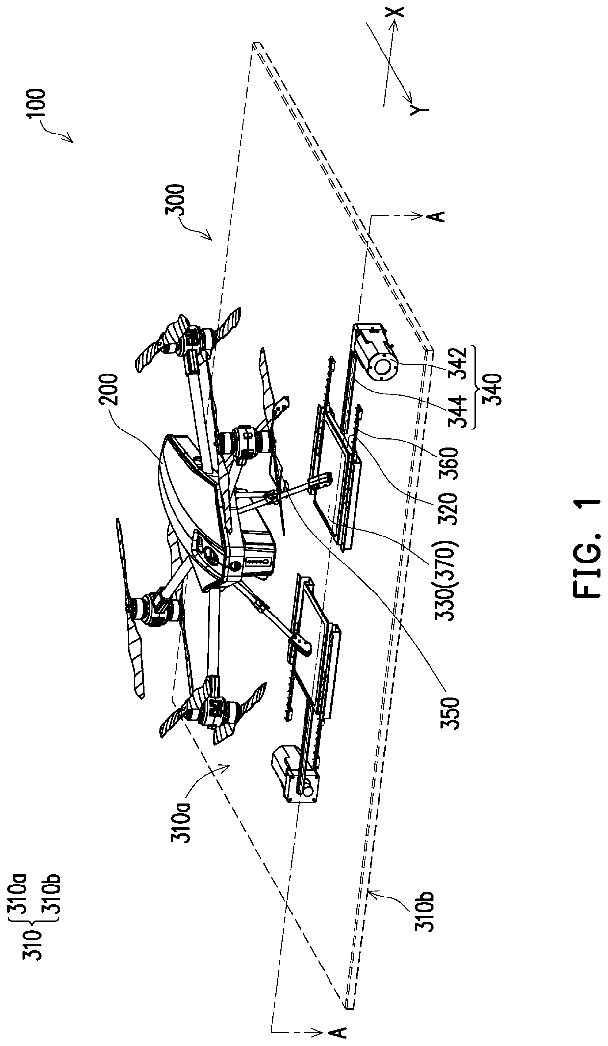
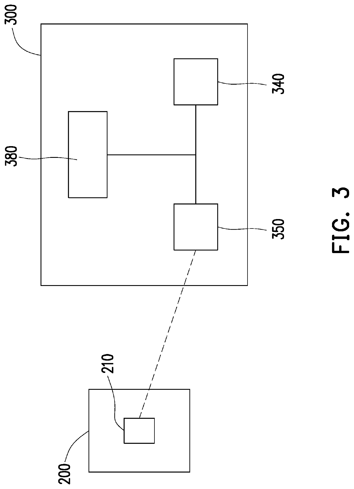
[0030]In the following detailed description of the preferred embodiments, reference is made to the accompanying drawings which form a part hereof, and in which are shown by way of illustration specific embodiments in which the invention may be practiced. In this regard, directional terminology, such as “top,”“bottom,”“front,”“back,” etc., is used with reference to the orientation of the Figure(s) being described. The components of the invention can be positioned in a number of different orientations. As such, the directional terminology is used for purposes of illustration and is in no way limiting. On the other hand, the drawings are only schematic and the sizes of components may be exaggerated for clarity. It is to be understood that other embodiments may be utilized and structural changes may be made without departing from the scope of the invention. Also, it is to be understood that the phraseology and terminology used herein are for the purpose of description and should not be ...


PUM


Abstract

A charging station, a charging system and a charging method for a drone are provided. The charging station adapted to park a drone for charging includes a parking ramp, a pair of charging plates, a pair of protecting covers, and at least one actuating device. The parking ramp has a parking surface and a bottom surface. The drone is parked on the parking surface having at least two openings. The charging plates are fixed to the bottom surface. The protecting covers are disposed between the bottom surface of the parking ramp and the charging plates. The protecting covers cover the charging plates at the openings. The actuating device is fixed to the bottom surface and connected to the protecting covers. When the drone stands still on the parking surface, the actuating device drives the protective covers to move relative to the charging plates to expose the charging plates.

Description

CROSS-REFERENCE TO RELATED APPLICATION[0001]This application claims the priority benefit of China application serial no. 201910079507.3, filed on Jan. 28, 2019. The entirety of the above-mentioned patent application is hereby incorporated by reference herein and made a part of this specification.BACKGROUNDField of the Invention[0002]The invention relates to a drone and more particularly, to a charging station, a charging system and a charging method for a drone.Description of Related Art[0003]A drone is a new emerging operating tool for business and industrial applications and is mainly applied in outdoor automatic flight patrol. Currently, an optical recognition system is commonly used to position a landing position when the drone flies back to a parking ramp and land after completing a task, so as to land accurately. For example, the optical recognition system may include techniques, such as an infrared (IR) camera technique and a computer vision (CV) technique. However, charging ...

Claims


Application Information

Patent Timeline
Patent Type & Authority Applications(United States)
IPC IPC(8): H02J7/00B64D45/08B64C39/02
CPCB64C2201/066B64C39/024H02J7/0045B64D45/08B60L53/30B60L53/14B60L53/37B64F1/00B64F1/20B60L2200/10Y02T10/70Y02T10/7072Y02T90/14Y02T90/12H02J7/0042
Inventor YANG, I-TACHENG, HSU-CHIHCHEN, YING-CHIEHHSIEH, CHI-TONG
Owner CORETRONIC INTELLIGENT ROBOTICS CORP
Why Eureka
Try Eureka