Electrophotographic developer and image-forming method using the developer

Inactive Publication Date: 2005-03-08
SHARP KK
View PDF13 Cites 0 Cited by
  • Summary
  • Abstract
  • Description
  • Claims
  • Application Information

AI Technical Summary

Benefits of technology

An object of the present invention is to provide an electrophotographic developer which reduces toner contamination on the surface of a developer carrier and maintains a charging efficiency in a high state even when narrowed is a mass part (development effective range) where an electrostatically charged-image holder is disposed oppositely to a developer carrier and which is stabilized in an image-quality in every environmental situation and has a long life and a low cost and an image-forming method using the above developer.
Intensive researches repeated by the present inventors in order to achieve the foregoing object in the present invention have resulted in establishing a system in which a good image can be obtained even in a development effective range in an electrostatically charged-image holder having a low radius of curvature and a small diameter by cutting particularly a small diameter mass part of a toner to sharpen a particle size distribution of the toner and obtaining a stable developer having a good charging property.
In the present invention, restriction of an amount of the toner having a small particle diameter, particularly the toner having a diameter of 6.35 μm or less makes it possible to inhibit fusion or adhering (spent toner) of the toner onto the developer carrier from being caused and to maintain atoner carrier surface fresh, and it maintains well a charging property of the toner fed and can provide effects of stabilizing the image quality and extending the life of the developer. Further, capable of being provided is an image-forming method particularly preferably used in a printing system in which a stable image quality is provided over a long period of time without being affected by a difference in an environmental situation and a use situation and in which a space is saved at a low running cost.

Problems solved by technology

However, a reduction in a particle diameter of a toner makes a production step thereof complicated and therefore leads to production at a high cost.
Usually, it is possible to readily obtain a toner having a volume average particle diameter of 8 to 12 μm by the crushing method described above, but further measures are required in order to obtain a toner particle size of 12 μm or less by the above crushing method, and the facilities become complicated.
This turns the above method into a method having an inferior productivity and a high cost.
Further, a polymerization method is used as a method for obtaining a toner having a small particle diameter, but various organic solvents are used in many cases, and waste water treating facilities therefor, complicated maintenance thereof and the inferior yield turn the above method into high cost production in terms of facilities therefor.
Further, it is very difficult to handle a toner having a small particle diameter because of specific powder characteristics thereof.
Brought about are a deterioration in the image caused by the inferior fluidity, particularly a degradation in the fluidity at a high temperature and a high humidity and a reduction in the image density caused by a rise in the charge amount at low temperature and a low humidity.
Further, continuing copy-printing in many sheets expedites a rise in the charge amount and causes fusion or adhesion of a toner on a carrier surface.
This markedly brings about an inhibition in charging, an increase in contamination in the machine caused by scattering of a toner, a rise in the background density and a deterioration in the image caused by a reduction in the image density and shortens a life of a developer.
As described above, a decrease in a particle diameter of a toner makes it possible to raise the image quality for a while but leads to a toner having a high cost and a short developing life.
Further, restriction and the construction of a new mechanism are required to the process conditions and the image-forming system themselves, which in turn can not help resulting in elevating a cost required for one sheet of a print.
In this case, troubles are more notably caused if a toner has a short developing time and an inferior developability, and the probability of the troubles results in growing large.
That is, remaining of the toner having a small particle diameter contaminates the surface of a toner carrier and brings about an inhibition in charging of the toner in the fresh developer fed, and it in turn causes various kinds of the problems described above.
However, the more the chance in which the developer is developed is increased, the larger the chance in which the toner transfers from the electrostatically charged-image holder into the developer carrier results in growing.

Method used


Image

  • Electrophotographic developer and image-forming method using the developer

Examples


examples

The present invention shall specifically be explained below with reference to examples.

Judging methods and judging criteria for the image density, the background density, toner scattering and carrier flying which were carried out in the following examples were carried out according to Table 1.

In this case, the image density shown in Table 1 was measured by means of a reflection densitometer (manufactured by Macbeth Co., Ltd.), and the background density was judged by measuring by means of a whiteness meter (manufactured by Nippon Denshoku Kogyo. Co., Ltd.). Toner scattering was evaluated by visually observing the degree of contamination caused by the toner in a mass part under a developer-feeding port in a developing bath. Carrier flying was judged by catching the toner on the electrostatically charged-image holder by means of a pressure-sensitive tape to count the number thereof (number / cm2).

Blending mass part or percentage is based on mass.

TABLE 1EvaluationJudging criteriaItemsJud...

example 2

A developer was obtained in the same manner as in Example 1, except that Toner B was used, and the same copying test was carried out. The respective evaluation, items were judged according to the judging criteria shown in Table 1, and the results thereof are shown by every environmental condition in Tables 3 to 5.

The stable results were shown to the image density, the background density, toner scattering and carrier flying on every environmental condition from the beginning through the life end (in copying 20,000 sheets).

example 3

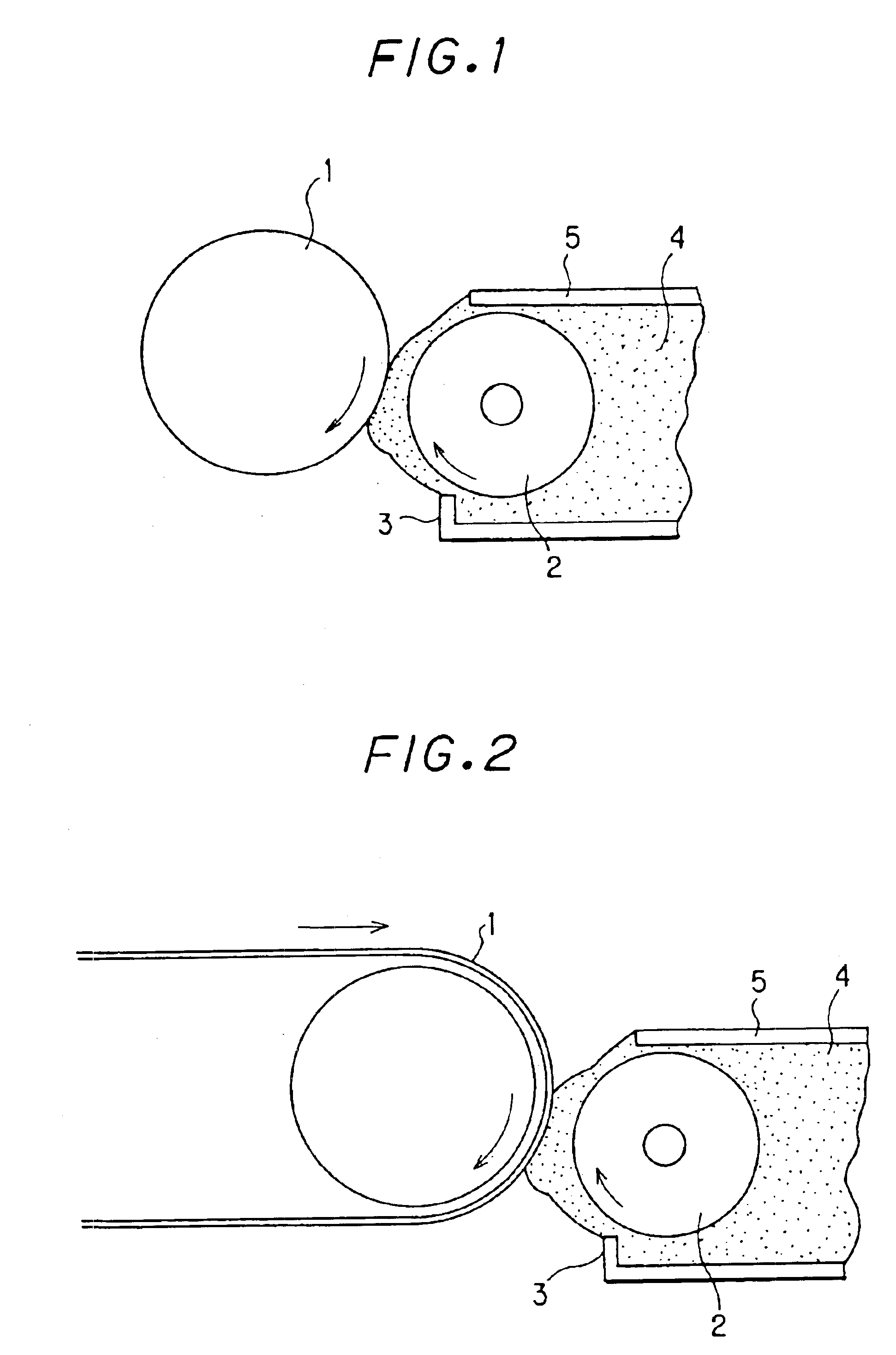
Toner A and a ferrite carrier I which was coated on a surface with an acryl-modified silicon resin and which had a weight average particle diameter of 9.5 μm were mixed for 15 minutes by means of the Nauter mixer so that the toner concentration became 5%, and the resulting developer was charged into a copying machine (a photoreceptor and a developer carrier rotate in directions reverse to each other in a developing area to carry out development) in which a head distance of the developer was controlled to 0.6 mm and a photosensitive belt had a radius of curvature of 18 mm in a developing area where the photosensitive belt was disposed oppositely to a developer carrier, in which the developer carrier had a radius of curvature of 12 mm and in which a minimum proximity distance between the photosensitive belt and the developer carrier was 0.8 mm and a ratio of a peripheral speed of an developer carrier to a peripheral speed of the electrostatically charged-image holder was 2.5, and copy...


PUM


Abstract

The present invention provides an electrophotographic developer which reduces toner contamination on the surface of a developer carrier even when a development effective range is narrowed and which is stabilized in an image quality in every environmental situation and has a long life and a low cost and an image-forming method using the same.In the present invention, used for the electrostatically charged-image holder described above having a radius of curvature of 18 mm or less in a development effective range is the electrophotographic developer which is a two-component developer comprising a toner comprising at least a binder and a colorant and a carrier which is coated with a resin and has a weight average particle diameter of 40 to 100 μm, wherein the above toner has a volume average particle diameter of 8 to 11.5 μm, and the toner particles having a diameter of 6.35 μm or less account for 20 number % or less.

Description

BACKGROUND OF THE INVENTION1. Field of the InventionThe present invention relates to an electrophotographic developer and an image-forming method using the above developer, specifically to an electrophotographic developer which can provide a good image when using an electrostatically charged-image holder (photoreceptor drum) having a small diameter and an image-forming method.2. Description of the Related ArtIn general, in an electrophotography, a toner having a prescribed charging property is developed with a developing unit in order to visualize a latent image formed on a photoreceptor. A toner image is fixed on paper by heating and pressing in a fixing system, whereby a copied image is obtained. In particular, large factors affecting an image quality and a grade of a copied image include a developing step for accurately developing an electrostatic latent image on an electrostatically-charged image holder, a transferring step for transferring the developed developer on a transferr...

Claims


Application Information

Patent Timeline
IPC IPC(8): G03G13/06G03G13/09G03G9/08G03G9/107G03G9/113
CPCG03G9/0819G03G13/09G03G9/1136G03G9/1075
Inventor ISHIDA, TOSHIHISAIMAFUKU, TATSUOSAITO, JUNICHIBITO, TAKAHIRO
Owner SHARP KK
Why Eureka
Try Eureka