Eureka AIR delivers breakthrough ideas for toughest innovation challenges, trusted by R&D personnel around the world.

Joint connector and busbar

Active Publication Date: 2020-08-06
SUMITOMO WIRING SYST LTD
View PDF0 Cites 0 Cited by
  • Summary
  • Abstract
  • Description
  • Claims
  • Application Information

AI Technical Summary

Benefits of technology

The patent describes a busbar body with alternating contact pieces that can be formed from a single plate, resulting in improved material yield and reduced manufacturing costs. The contact pieces are cut and raised from the busbar body, and a frame is provided outside the contact pieces to ensure strength. The busbar body can be connected to general-purpose female and male terminal fittings, allowing for a wider range of mating terminals. The technical effect is an improved and cost-effective design for busbars.

Problems solved by technology

However, if the busbar has the double-plate structure, a material yield is poor, thereby causing a problem of high manufacturing cost.
Further, the first and second contact pieces are provided by cutting and raising, and it is difficult to ensure strength.

Method used


Image

  • Joint connector and busbar
  • Joint connector and busbar
  • Joint connector and busbar

Examples


Embodiment Construction

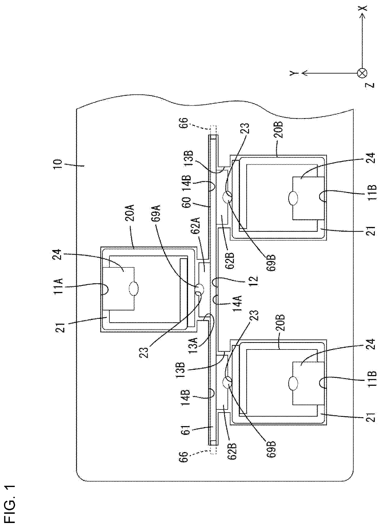
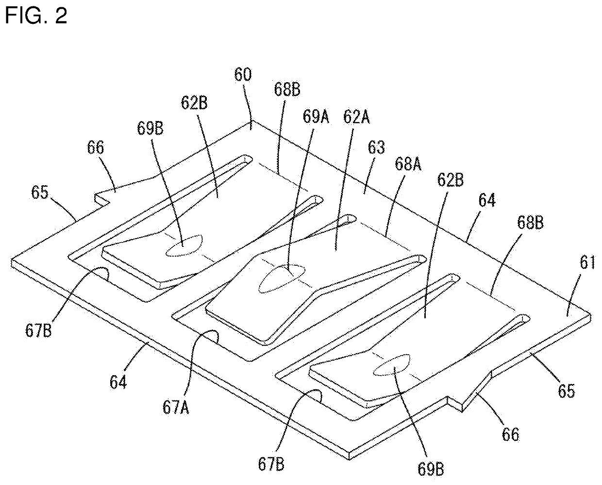
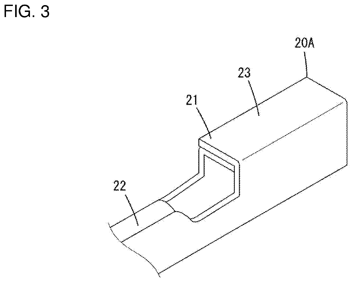
[0014]One embodiment of the invention is described with reference to FIGS. 1 to 3. As shown in FIG. 1, a joint connector of this embodiment includes a housing 10, a first terminal 20A and second terminals 20B accommodated in the housing 10 and a busbar 60 likewise accommodated in the housing 10 for short-circuiting the first terminal 20A and the second terminals 20B. The housing 10 is fittable to an unillustrated mating housing. Unillustrated mating first terminal and mating second terminals are accommodated in this mating housing. When the housing 10 is fit to the mating housing, the first terminal 20A is connected to the mating first terminal, the second terminals 20B are connected to the mating second terminals and these terminals are joined via the busbar 60. The busbar 60 is accommodated into the housing 10 accommodating the first terminal 20A and the second terminals 20B instead of in a dedicated relay housing. Thus, the configuration is simplified.

[0015][Housing 10]

[0016]The ...


PUM


Abstract

A housing (10) has a mounting groove (12) between a first cavity (11A) in a first stage and second cavities (11B) in a second stage. A first communication portion (13A) allows communication between the mounting groove (12) and the first cavity (11A), Second communication portions (13B) allow communication between the mounting groove (12) and the second cavities (11B). A first terminal (20A) is accommodated in the first cavity (11A), and second terminals (20B) are accommodated in the second cavities (11B). A busbar (60) includes a plate-shaped body (61) accommodated in the mounting groove (12). A first contact piece (62A) integrally projects from the busbar body (61) toward the first stage and enters the communication portion (13A) to contact the first terminal (20A), and second contact pieces (62B) integrally project from the busbar body (61) toward the second stage and enter the communication portions (13B) and contact the second terminals (20B).

Description

BACKGROUNDField of the Invention[0001]The invention relates to a joint connector and a busbar.Related Art[0002]Japanese Unexamined Patent Publication No. H10-255935 discloses a joint connector with a connector housing having terminal accommodation chambers and a plate accommodating portion. Terminal fittings are accommodated in the respective terminal accommodation chambers and a busbar is accommodated in the plate accommodating portion for connecting the respective terminal fittings in a short-circuit state. The terminal accommodation chambers are provided side by side in the connector housing and are at the same interval in a column direction in upper and lower stages. The plate accommodating portion is provided between the upper and lower terminal accommodation chambers and includes a communication part communicating with the respective terminal accommodation chambers. The busbar has a double-plate structure formed by folding a metal plate. The busbar includes a coupling piece, w...

Claims


Application Information

Patent Timeline
IPC IPC(8): H01R31/08H01R13/428H01R43/16
CPCH01R13/428H01R43/16H01R31/085H01R31/08H01R13/10H01R2105/00
Inventor FUKATSU, YUKIHIROSAKURAI, TOSHIKAZU
Owner SUMITOMO WIRING SYST LTD
Why Eureka
Eureka Blog
Learn More