Power system stability analysis device, stabilization apparatus, and method

a technology of stability analysis and power system, which is applied in the direction of instruments, computer control, process and machine control, etc., can solve the problems of insufficient monitoring function and measurement accuracy of power system, inability to accurately estimate inability to predict the stability of the system, so as to prevent excessive and insufficient power supply restrictions, improve the accuracy of synchronous stability results, and reduce the accuracy of obtained estimation results

Active Publication Date: 2020-08-06
HITACHI LTD
View PDF0 Cites 4 Cited by
  • Summary
  • Abstract
  • Description
  • Claims
  • Application Information

AI Technical Summary

Benefits of technology

[0013]According to the present invention, in a case where the calculation of the state estimation does not converge or the accuracy is low, it is possible to prevent excessive and insufficient power supply restrictions of the power system stabilization apparatus by using the measurement value of the high-accuracy measurement device to improve the accuracy of the synchronous stability result.

Problems solved by technology

When the system state estimation calculation does not converge, there is a problem that a large error occurs between a current system state and the calculated value in a previous calculation, and the reliability of the obtained estimation result decreases.
In particular, this problem is likely to occur in areas where the monitoring function and measurement accuracy of the power system are insufficient.
When the reliability of the estimation result decreases, the reliability of the synchronous stability analysis of the power system also decreases.
In a power system stabilization apparatus, for example, if an incorrect synchronous stability analysis result is input and a power-controlled generator is determined, appropriate power control for preventing a power failure cannot be taken, and there is a risk of power failure.

Method used


Image

  • Power system stability analysis device, stabilization apparatus, and method
  • Power system stability analysis device, stabilization apparatus, and method
  • Power system stability analysis device, stabilization apparatus, and method

Examples


example 1

[0027]Example 1 of the present invention will be described below.

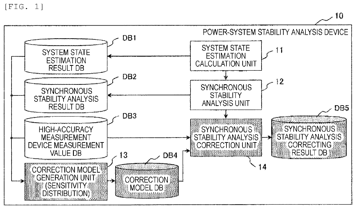
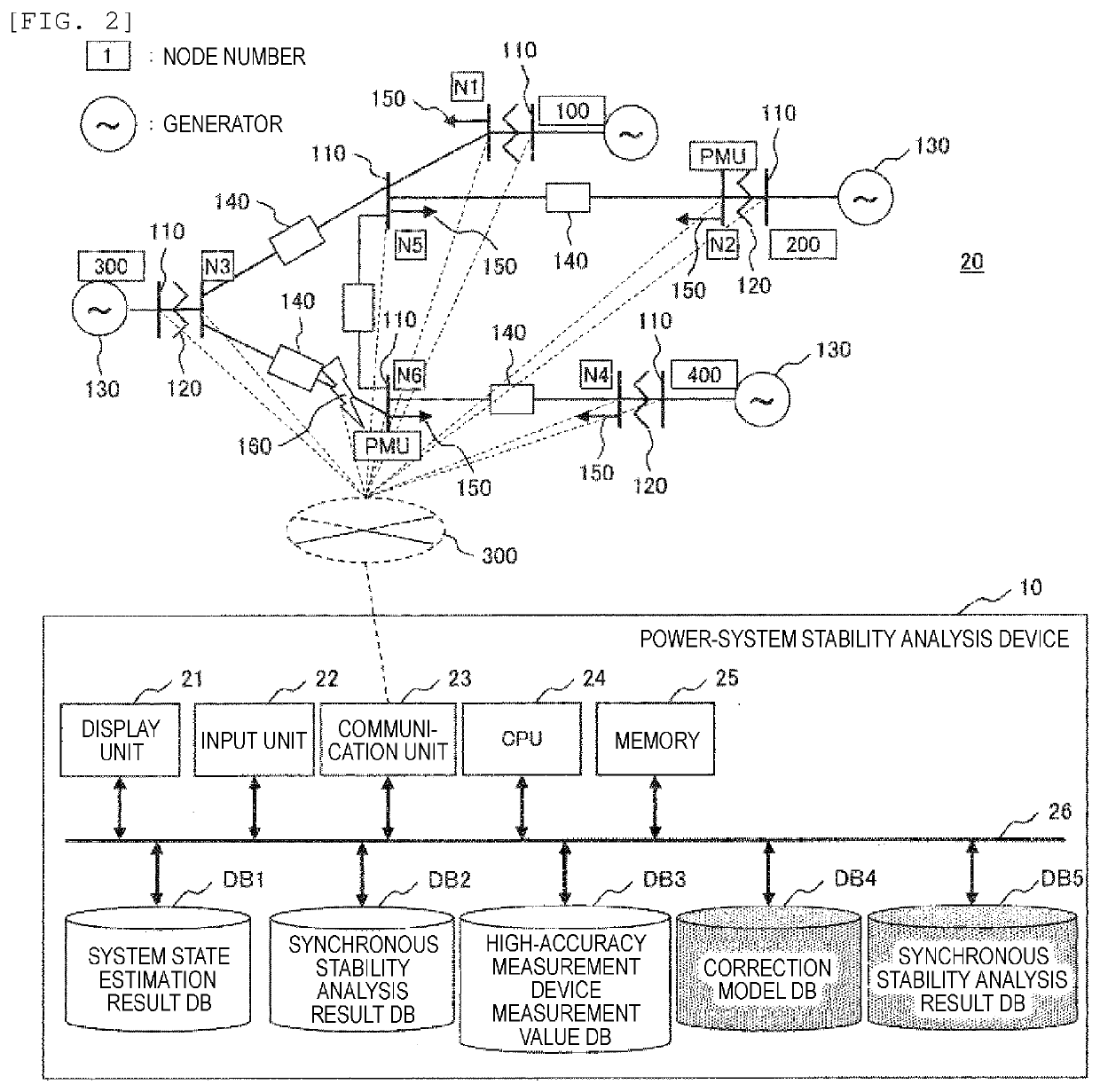
[0028]First, an example of a typical power system to which an example of the present invention can be applied and an example of a hardware configuration of a power system stability analysis device according to the example of the present invention will be described with reference to FIG. 2. The upper part of FIG. 2 illustrates a configuration example of a power system, and the lower part of FIG. 2 illustrates an example of a hardware configuration of a stabilization apparatus. An example of the configuration of the power system in the upper part will be described.

[0029]In the upper part of FIG. 2, a power system 20 is a system in which a plurality of generators 130 and loads 150 are interconnected via buses (nodes) 110, transformers 120, transmission lines 140, and the like. In FIG. 2, a reference numeral 160 indicates a location of an assumed failure in the power system.

[0030]In FIG. 2, node numbers N (N1, N2, N3, N4, ...

example 2

[0066]Example 2 of the present invention will be described below. Example 2 is an example of a power system stabilization apparatus 30 in which the processing result of the stability analysis device of Example 1 is applied to power supply restriction. A description overlapping with the content described in Example 1 will be omitted.

[0067]The power system stabilization apparatus 30 of Example 2 illustrated in FIG. 7 is an apparatus for stabilizing a power system by adding a power supply restriction determination unit and a power supply restriction table-use database correspondence database DB6 to the power system stability analysis device 10 of Example 1.

[0068]Here, the power supply restriction determination unit 15 determines an appropriate power-controlled generator for preventing a power failure from the synchronous stability result. The determined power-controlled generator is loaded and stored in the power supply restriction table-use database correspondence database DB6 as a po...

example 3

[0075]Example 3 of the present invention will be described below.

[0076]The power system stabilization apparatus 30 of Example 3 illustrated in FIG. 11 is a power system stabilization apparatus in which a synchronous stability analysis result selection unit 16 is added to the power system stabilization apparatus 30 of Example 2. A description overlapping with the content described in Example 2 will be omitted.

[0077]In the power system stabilization apparatus 30 of FIG. 11, the added synchronous stability analysis result selection unit 16 determines which value to use before correction or after correction. For example, if the difference between the measurement value of the high-accuracy measurement device and the system state estimation result is equal to or greater than the threshold value, the corrected value is used.

[0078]FIG. 12 is an example of a flowchart illustrating the processing of the power system stabilization apparatus in which the processing step S500 of selecting a sync...


PUM


Abstract

There is provided a power system stability analysis device that analyzes stability of a power system by obtaining measurement data from a high-accuracy measurement device and existing measuring instruments installed in the power system, the apparatus including: a system state estimation unit that estimates a system state of the power system by using measurement data from the existing measuring instruments at a plurality of points in the power system; a synchronous stability analysis unit that analyzes synchronous stability in an assumed failure by using an estimation result of the system state; and a synchronous stability analysis correction unit that corrects the synchronous stability according to a difference between the estimation result of the system state and the measurement data of the high-accuracy measurement device to improve accuracy of synchronous stability analysis of the power system.

Description

TECHNICAL FIELD[0001]The present invention relates to a power system stability analysis device, a stabilization apparatus, and a method.BACKGROUND ART[0002]As a background art in this technical field, there is disclosed in U.S. Pat. No. 8,190,379 (PTL 1). It is important to correctly understand the power flow state (active power P, reactive power Q, voltage V, voltage phase δ) of a power system for power system stability analysis. By reproducing a state close to a current power system with an analysis model, it is possible to predict the state of the power system in the event of a failure and to perform a stabilization measure in preparation for a power system failure in advance. In general, the state of the power system is grasped by a system state estimation calculation using measurement values (active power P, reactive power Q, voltage magnitude V, voltage phase δ, current I, and the like) of the amount of electricity measured by a measurement sensor installed in the power system...

Claims


Application Information

Patent Timeline
Patent Type & Authority Applications(United States)
IPC IPC(8): H02J3/24H02J13/00G05B15/02
CPCG05B15/02H02J13/00002H02J3/24H02J2203/20Y04S20/00Y02B90/20H02J3/242Y04S10/22Y02E40/70Y02E60/00
Inventor TSUJII, YUKIKUMAGAI, MASATOSHIKAWAKITA, KENEDWARDWATANABE, MASAHIRO
Owner HITACHI LTD
Why Eureka
Try Eureka