Electric motor with liquid cooled rotor

Inactive Publication Date: 2020-08-06
WOODY GEORGE R +2
View PDF0 Cites 5 Cited by
  • Summary
  • Abstract
  • Description
  • Claims
  • Application Information

AI Technical Summary

Benefits of technology

[0009]The present disclosure describes an innovative highly efficient liquid cooled electric motor apparatus. Similar to the previously disclosed liquid cooled rotor assemblies, the present disclosure includes a hollow rotor shaft through which a liquid coolant can flow. However, unlike previous co

Problems solved by technology

This innovative feature significantly increases the heat transfer surface area that comes in

Method used


Image

  • Electric motor with liquid cooled rotor
  • Electric motor with liquid cooled rotor
  • Electric motor with liquid cooled rotor

Examples


Embodiment Construction

[0034]The above described drawing figures illustrate an exemplary embodiment of presently disclosed apparatus and its many features in at least one of its preferred, best mode embodiments, which is further defined in detail in the following description. Those having ordinary skill in the art may be able to make alterations and modifications to what is described herein without departing from its spirit and scope of the disclosure. Therefore, it must be understood that what is illustrated is set forth only for the purposes of example and that it should not be taken as a limitation in the scope of the present apparatus or its many features.

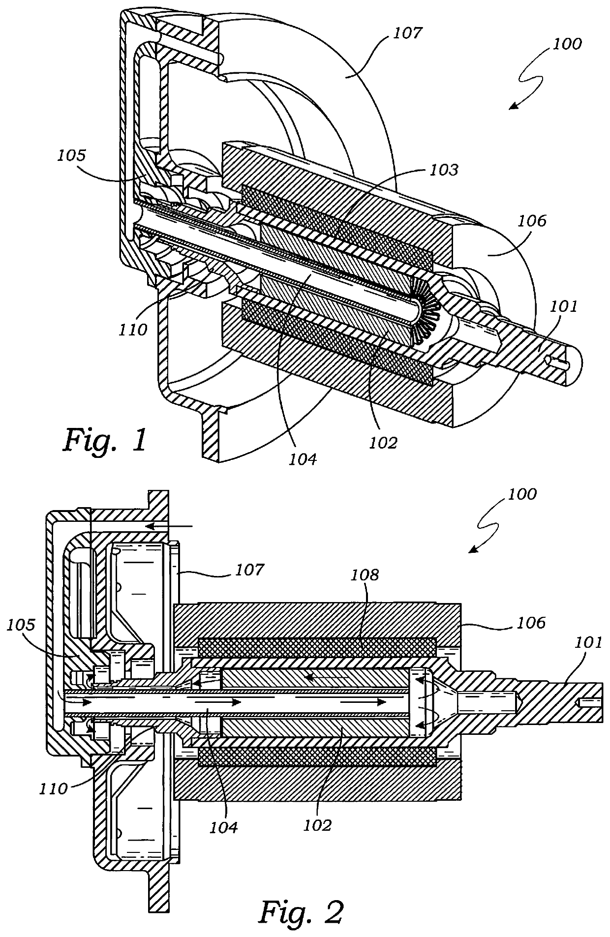
[0035]Described now in detail is an efficient electric traction drive motor with an innovative liquid cooled rotor capable of enhanced thermal dissipation resulting in greater performance and power density.

[0036]FIG. 1 illustrates an exemplary cut away perspective of the presently disclosed apparatus 100 featuring a stationary coolant tube 104 held i...


PUM


Abstract

An electric drive motor with an improved liquid cooling system featuring a hollow rotor shaft configured to allow liquid coolant to flow in and out of the rotor shaft through an aperture in one distal end following a path influenced by a coolant tube such that the liquid coolant is directed to flow past a plurality of internally located heat dissipation fins which are in thermal communication with the rotor shaft thereby increasing the heat dissipation, performance, and power density.

Description

FIELD OF THE PRESENT DISCLOSURE[0001]This disclosure relates generally to electric motor technology and more specifically to an electric traction drive motor with an innovative liquid cooled rotor capable of enhanced thermal dissipation resulting in improved performance and power density.BACKGROUND OF THE RELATED ART[0002]As electric motor technology advances, electric motors are being used in an increasing number of applications, many of which require high performance and high efficiency. In such high demanding applications, the ability to quickly dissipate heat is extremely important because as performance demands on an electric motors increase, heat generation typically increases as well. The increased heat can be a performance limiting factor if it is not adequately dissipated; therefore, innovative and more efficient heat dissipation techniques are at the forefront of electrical motor advances. This is especially true with induction motors which tend to generate more heat in th...

Claims


Application Information

Patent Timeline
IPC IPC(8): H02K9/19H02K9/22H02K5/20H02K5/18
CPCH02K9/19H02K5/20H02K9/22H02K5/18H02K1/32H02K9/227H02K5/203H02K9/197
Inventor WOODY, GEORGE R.CAROSA, PAUL F.CHANG, HARRY X.
Owner WOODY GEORGE R
Why Eureka
Try Eureka