
Holder for mounting a second part on a main structure between car body ends of a rail vehicle

Pending Publication Date: 2020-08-13
DELLNER COUPLERS AB
View PDF0 Cites 1 Cited by
  • Summary
  • Abstract
  • Description
  • Claims
  • Application Information

AI Technical Summary

Benefits of technology

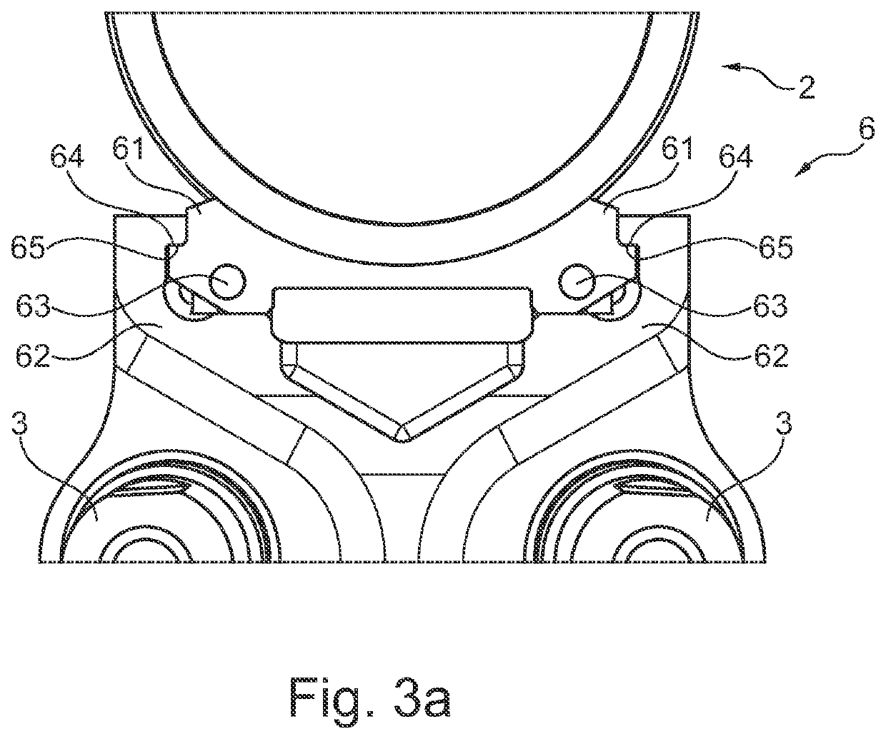
The present invention is addressing issues associated with holding devices by introducing a holder with inclined surfaces that are pressed together in a mounted state. This leads to significantly smaller bending forces, minimizing fatigue risks and allowing for effective force management. Additionally, the fastening device for the holder is designed to create a holding force in a first direction, parallel to the horizontal axis, reducing loads on the fastening device. The screw and nut components of the fastening device cooperate to create a stable and secure holding, with the option for release in case of large forces. The horizontal axis runs along the screw to minimize wear and tear on it. The angle between the two surfaces is less than 10 degrees to efficiently absorb bending forces.

Problems solved by technology

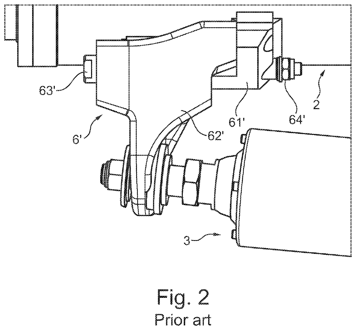
As a result, sacrificial components need to be replaced frequently, leading to additional costs.
There are prior art solutions that attempt to provide such support but they generally suffer from considerable drawbacks, especially since some of the components may break due to fatigue arising from bending forces generated during operation of the train set.

Method used


Image

  • Holder for mounting a second part on a main structure between car body ends of a rail vehicle
  • Holder for mounting a second part on a main structure between car body ends of a rail vehicle
  • Holder for mounting a second part on a main structure between car body ends of a rail vehicle

Examples


Embodiment Construction

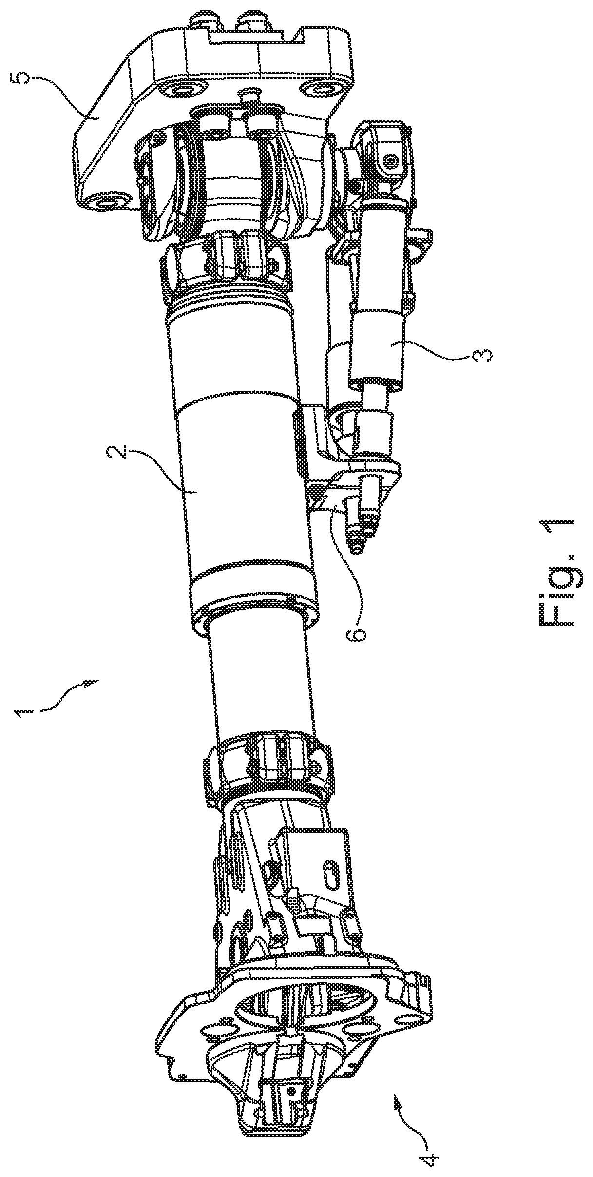
[0027]The invention relates to a holder suitable for mounting a second part on a main structure between car body ends of a rail vehicle. The main structure may be a main buffer, coupler head or car body attachment, while the second part may be support dampers, a gangway support or an electrical coupler, among others. The part or parts may be included in a coupler, damper, gangway support or a pneumatic block, or any other structure suitable for placement between car body ends. The cars may be railway vehicles intended to be coupled to each other to form a train set, but may also be other car bodies for a rail vehicle that are to be coupled to each other. If the main structure is a main buffer having support dampers mounted thereon, the holder is configured to offer vertical support to the main buffer.

[0028]FIG. 1 discloses a coupler 1 for coupling car body ends to each other, the coupler 1 having a main buffer 2 mounted between a coupler head 4 and a car body attachment 5. The car b...


PUM


Abstract

The present invention relates to a holder for mounting a second part on a main structure between car body ends of a rail vehicle, comprising —a first holding structure having a first contact surface, the first holding structure being configured to be attached to a main structure; —a second holding structure having a second contact surface, the second holding structure being configured to be attached to a second part, and the second holding structure further being arranged to be mounted on the first holding structure with one of the first and second contact surfaces resting on the other; —a fastening device for fastening the second holding structure to the first holding structure to form a mounted state, the first and second contact surfaces being pressed against each other in the mounted state, and wherein the first and second contact surfaces in the mounted state each extend at a first angle in relation to a horizontal axis, said first angle (α) being more than 1 degree and less than 30 degrees, and wherein the fastening device (53) extends in a direction parallel to or coinciding with the horizontal axis (A).

Description

TECHNICAL FIELD[0001]The present invention relates to a holder for mounting a second part on a main structure between car body ends of a rail vehicle, comprising[0002]a first holding structure having a first contact surface, the first holding structure being configured to be attached to a main structure;[0003]a second holding structure having a second contact surface, the second holding structure being configured to be attached to a second part, and the second holding structure further being arranged to be mounted on the first holding structure with one of the first and second contact surfaces resting on the other;[0004]a fastening device for fastening the second holding structure to the first holding structure to form a mounted state, the first and second contact surfaces being pressed against each other in the mounted state.BACKGROUND[0005]When coupling car bodies of trains together, a coupler is generally used to connect the two car bodies to each other. A number of parts are arr...

Claims


Application Information

Patent Timeline
IPC IPC(8): B61G7/10B61G5/08
CPCB61G9/22B61G3/16B60L2200/26B61G5/10B61G5/08B61G7/10B61G9/20B61G7/12
Inventor GRAHN, ARVIDHARRYSSON, FREDRIK
Owner DELLNER COUPLERS AB
Learn More