Method and device for up-sampling a point cloud

a point cloud and up-sampling technology, applied in the field of point cloud data sources, can solve the problems of large storage space occupation, large amount of point clouds, and invariably noisy point clouds captured using commercial laser range scanners,

Active Publication Date: 2020-08-13
INTERDIGITAL VC HLDG INC
View PDF0 Cites 0 Cited by
  • Summary
  • Abstract
  • Description
  • Claims
  • Application Information

AI Technical Summary

Benefits of technology

[0031]This means that the higher the number of distance-S neighbors of the neighboring point, the more possible that this neighboring point will be added to the point cloud.

Problems solved by technology

Scanned 3D point clouds often have thousands of points and occupy large amounts of storage space.
It happens that some point clouds, for instance captured using commercial laser range scanners are invariably noisy, mostly caused by scanner artifacts and alignment errors between scans.
In addition, occluded or sharp regions are often under-sampled.
Due to noise and under-sampling, a direct rendering or surface reconstruction of raw points produces grainy surfaces, gaps and holes, and irregular boundaries.
These artifacts are especially visually-disturbing and must be corrected by a post-processing including an up-sampling which is a process of inserting samples between original samples of the dataset in order to increase the sampling rate of the whole dataset or several parts of the dataset.
The under-sampling problem is worse in the case of dynamic point cloud compression where the under-sampled parts of the point clouds which are compressed by an intra coding mode could significantly jeopardize the codec performance.
Polynomial fitting operation is computationally complex.
Thus, the polynomial fitting based up-sampling schemes of point clouds are not suitable for use-cases that require low complexity, such as on-the-fly point cloud rendering and point cloud decoding.

Method used


Image

  • Method and device for up-sampling a point cloud
  • Method and device for up-sampling a point cloud

Examples


second embodiment

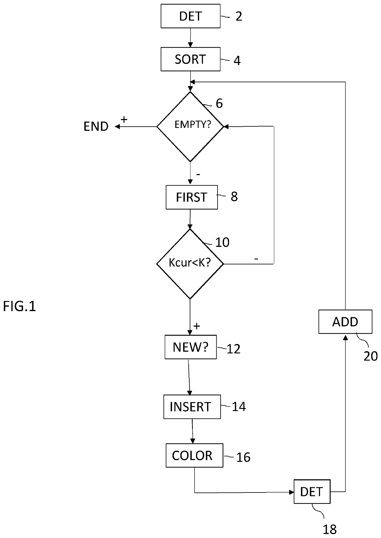
[0077] the range of neighborhood within which new points will be added around each under-sampled point is determined as:

SFill={1,ifKP1>ThresAdaptiveRangetheminimumvaluethatsatisfiesKPSFillP>ThresFill,ifKP1≤ThresAdaptiveRange

where KP1 is the number of distance 1 neighbors of the under-sampled point and KPSFill is the number of distance SFill neighbors of the under-sampled point and where ThresAdaptiveRange and ThresFill are predetermined thresholds, for example ThresAdaptiveRange=2, ThresFill=8.

[0078]This second embodiment requires less computational complexity as it does not need to recursively process the new points just generated during the process.

[0079]During this step 12, the local tangent plane of the under-sampled point is calculated.

[0080]The considered under-sampled point is a point belonging to an under-sampled region and is denoted as PUnderSampled.

[0081]The local tangent plane of PUnderSampled is determined using the distance-SNormal neighbors of PUnderSampled. As ...

first embodiment

[0089] for each of the un-occupied distance-S neighbors, PUnOccupi, of PUnderSampled, its possibility of being inserted around PUnderSampled is determined based on the following 3 factors.

1. 1st Factor

[0090]The first factor is |{NeighDisSi}|, the number of the distance-S neighbors of PUnOccup.

[0091]This factor penalizes those potential new points requiring inserting more points around them. The higher |{NeighDisSi}| is, the more possible that PUnOccupi will be added to the point cloud.

2. 2nd Factor

[0092]According to a first variant, the second factor is the change of the distance between the further neighborhood and the local neighborhood of PUnderSampled if PUnOccupi is inserted, denoted as DisChangeNeighborhoodi.

[0093]The distance between the further and the local neighborhoods of PUnderSampled is defined by

DisNeighborhood=∑{NeighFutherm}min{NeighLocaln}(NeighFurtherm-NeighLocaln),

where {NeighLocaln} and {NeighFurtherm} are the local and further neighborhoods of PUnderSampled, i.e...


PUM


Abstract

This method for up-sampling a point cloud representing a 3D object, comprises:—detecting (2) points belonging to at least one under-sampled region of the point cloud on the basis of at least one desirable sampling rate (K);—obtaining (12), for each detected point, an associated tangent plane;—inserting (14) in the point cloud at least one neighboring point of each detected point if a distance between the neighboring point and the tangent plane associated with the detected point is less than a first threshold.

Description

FIELD OF THE DISCLOSURE[0001]The present disclosure generally relates to the field of point cloud data sources that represent 3D objects.[0002]More particularly, it deals with the post-processing of point clouds.[0003]Thus, the disclosure concerns a method for up-sampling a point cloud and a corresponding device. It also concerns methods for encoding and decoding a point cloud and corresponding encoder and decoder. It further concerns a computer program implementing the up-sampling method of the invention.BACKGROUND OF THE DISCLOSURE[0004]The approaches described in this section could be pursued, but are not necessarily approaches that have been previously conceived or pursued. Therefore, unless otherwise indicated herein, the approaches described in this section are not prior art to the claims in this application and are not admitted to be prior art by inclusion in this section.[0005]A point cloud consists in a set of points usually intended to represent the external surface of a 3...

Claims


Application Information

Patent Timeline
Patent Type & Authority Applications(United States)
IPC IPC(8): G06T9/00G06T19/20
CPCG06T19/20G06T9/00G06T2210/56G06T2219/2012G06T17/00
Inventor CAI, KANGYINGGUEDE, CELINELLACH PINSACH, JOANLASSERRE, SEBASTIEN
Owner INTERDIGITAL VC HLDG INC
Why Eureka
Try Eureka