Shaping method and shaping device

a shaping device and shape technology, applied in the direction of manufacturing tools, additive manufacturing processes, manufacturing data acquisition/processing, etc., can solve the problem of visual recognition of the color of the shape object, and achieve the effect of improving the visual recognition of the shape obj

Inactive Publication Date: 2020-08-20
MIMAKI ENG
View PDF0 Cites 0 Cited by
  • Summary
  • Abstract
  • Description
  • Claims
  • Application Information

AI Technical Summary

Benefits of technology

[0007]The present disclosure thus provides a shaping method and a shaping device that prevent an interior layer from affecting the color of the shaped object visually recognized from the outside.
[0017]The present disclosure can prevent the interior layer from affecting the color of the shaped object visually recognized from the outside.

Problems solved by technology

However, if the thickness of the lower layer of the colored layer that forms the surface of the shaped object is not an appropriate thickness, the color of the interior layer and the hollowing of the interior layer may affect the color of the shaped object visually recognized from the outside.

Method used


Image

  • Shaping method and shaping device
  • Shaping method and shaping device
  • Shaping method and shaping device

Examples


first embodiment

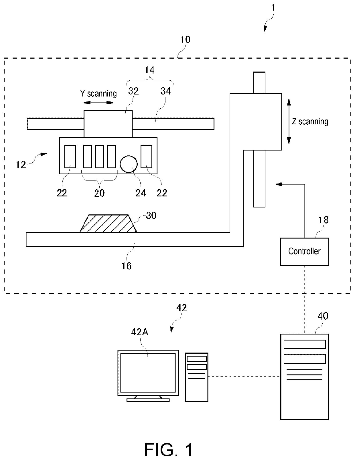
[0030]Hereinafter, a first embodiment of the present disclosure will be described. FIG. 1 is a view showing a configuration of a 3D printer system 1. The 3D printer system 1 includes a 3D printer 10, a control PC 40, and a user PC 42.

[0031]The 3D printer 10 is a shaping device of an inkjet method that includes an ejection unit 12, a main scan driver 14, a shaping table 16, and a controller 18, and that shapes a shaped object 30 by solidifying an ultraviolet curable resin sprayed from the ejection unit 12 with ultraviolet light and layering the ultraviolet curable resin.

[0032]The ejection unit 12 includes an ink head 20 that ejects colored and colorless ink to become the material of the shaped object 30 and ink containing a support material, an ultraviolet light source 22 that cures the ejected ink, and a flattening roller 24 that flattens the layered surface of the curable resin formed during the shaping of the shaped object 30. In the example of FIG. 1, three ink heads 20 are shown...

second embodiment

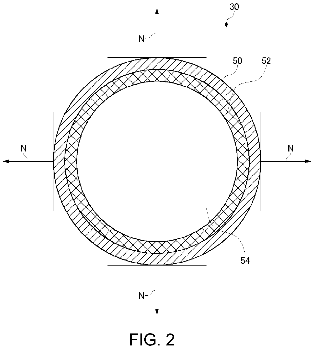
[0072]Hereinafter, a second embodiment of the present disclosure will be described. In the shaping method of the present embodiment, when the lower layer of the color layer 50 is the cavity 54A, the combined thickness of the color layer 50 and the reflection layer 52 is set to a thickness that can maintain the mechanical strength of the shaped object 30. Accordingly, the amount of material for forming the shaped object 30 can be reduced while maintaining the shape of the shaped object 30 even if the interior of the shaped object 30 is the cavity 54A.

[0073]In the present embodiment, the color layer 50 and the reflection layer 52 are collectively referred to as an outer contour layer, and the thickness of the outer contour layer is referred to as an outer contour thickness. In the present embodiment, the outer contour layer thickness is a thickness that maintains the mechanical strength of the shaped object 30, and is defined according to the size of the shaped object 30, the size of ...

third embodiment

[0095]Hereinafter, a third embodiment of the present disclosure will be described. In the present embodiment, the thickness of the reflection layer 52 is determined in accordance with a built-in element built in the lower layer of the reflection layer 52. The shaped object 30 utilizing the action of the built-in element thus can be formed.

[0096]FIG. 11 is a schematic view showing a cross-section of a shaped object 30 incorporating a light emitting body 72 as an example of a built-in element. The light emitting body 72 is, for example, an LED (Light Emitting Diode) device or an object having a light accumulating function. In the shaped object 30, the interior layer 54 is formed as a cavity 54A in order to place the light emitting body 72 inside. Thus, when the light emitting body 72 is the built-in element, it is desirable that the light emission from the light emitting body 72 can be visually recognized from the outside of the shaped object 30.

[0097]Therefore, in the example of FIG....


PUM

PropertyMeasurementUnit
thicknessaaaaaaaaaa
thicknessaaaaaaaaaa
thicknessaaaaaaaaaa

Abstract

The shaping method of the present embodiment is a shaping method for a shaped object configured to include at least a color layer that is colored and that forms the surface of the shaped object, and a reflection layer that forms the lower layer of the color layer, and determines the thickness of the reflection layer with a normal direction with respect to an outer contour of the shaped object as a reference. According to the present configuration, the thickness of the reflection layer is set to a thickness enough to reflect the color of the color layer so that an interior layer can be prevented from affecting the color of the shaped object visually recognized from the outside even if an interior layer formed under the reflection layer is formed of an arbitrary color or material.

Description

CROSS REFERENCE TO RELATED APPLICATIONS[0001]This application claims the priority benefit of Japanese Patent Application No. 2019-025752, filed on Feb. 15, 2019. The entirety of the above-mentioned patent application is hereby incorporated by reference herein and made a part of this specification.TECHNICAL FIELD[0002]The present disclosure relates to a shaping method and a shaping device.DESCRIPTION OF THE BACKGROUND ART[0003]In recent years, use of a shaping device (3D printer) that ejects ink to shape a three-dimensional object is being advanced. Such a shaping device performs shaping through a layered shaping method in which a plurality of ink layers is overlapped.[0004]Here, a large shaped object requires a large amount of material such as ink to use for shaping. Therefore, Japanese Unexamined Patent Publication No. 2007-71154 (i.e., Patent Literature 1) discloses a method of shaping a shaped object interiorly including a cavity. Thus, the material used for shaping can be reduce...

Claims


Application Information

Patent Timeline
Patent Type & Authority Applications(United States)
IPC IPC(8): B29C64/10
CPCB33Y10/00B29C64/10B33Y80/00B29C64/393B29C64/112B33Y50/02
Inventor KAZAANA, TAKEAKI
Owner MIMAKI ENG
Why Eureka
Try Eureka