
Linear friction welding machine

a welding machine and friction welding technology, applied in welding equipment, non-electric welding equipment, manufacturing tools, etc., can solve the problems of unfavorable linear friction welding, limited production speed, and inability to use in a practical manner, and achieve high production speed, small cross sectional area, and simple construction

Active Publication Date: 2020-08-27
PEWAG AUSTRIA
View PDF0 Cites 0 Cited by
  • Summary
  • Abstract
  • Description
  • Claims
  • Application Information

AI Technical Summary

Benefits of technology

The invention is a linear friction welding machine that is suitable for small parts and has a simple construction that allows for high production speed. The machine uses wear-free and durable mechanical elements to manage the oscillating movements and support the pressures and forces released during the welding process. This results in a cost-effective and efficient machine that can be installed easily and operate at high frequencies without any problem.

Problems solved by technology

In this case, however, on the friction surfaces an uneven heating occurs inside the respective friction surface owing to the different angular speeds over the cross section of the respective friction surface, with the consequence of an also uneven strength distribution in the weld points, wherein only rotationally symmetrical cross sections can be welded to each other.
This known friction welding machine may certainly able to be used for the friction welding of the end surfaces of two parts with large longitudinal extent, e.g. rails inter alia, with profiled cross sections, but is costly owing to the translational relative movement, initiated in the friction surface, of the end surfaces of the parts to be interconnected by means of a corresponding eccentric drive of the clamping means, which clamps the ends of the parts, via a corresponding motor-driven rotational axis and cannot be used in a practical manner for carrying out a linear friction welding of relatively small cross sectional areas, such as when welding parts of chain links to each other.
Also, the eccentric drive used here does not permit the generation of a high oscillation frequency, which limits the production speed.

Method used


Image

  • Linear friction welding machine
  • Linear friction welding machine

Examples


Embodiment Construction

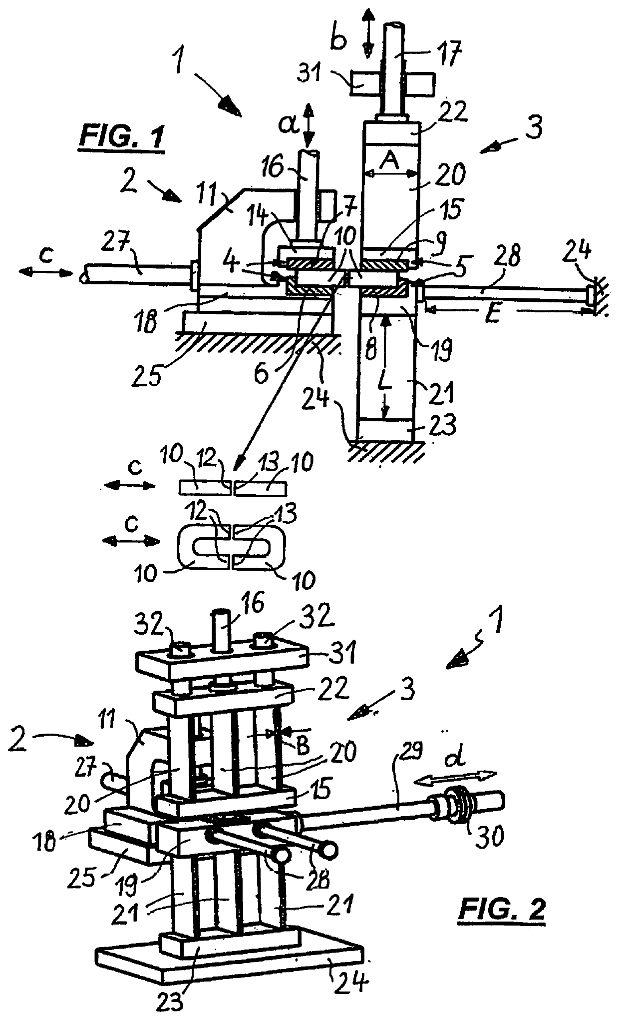
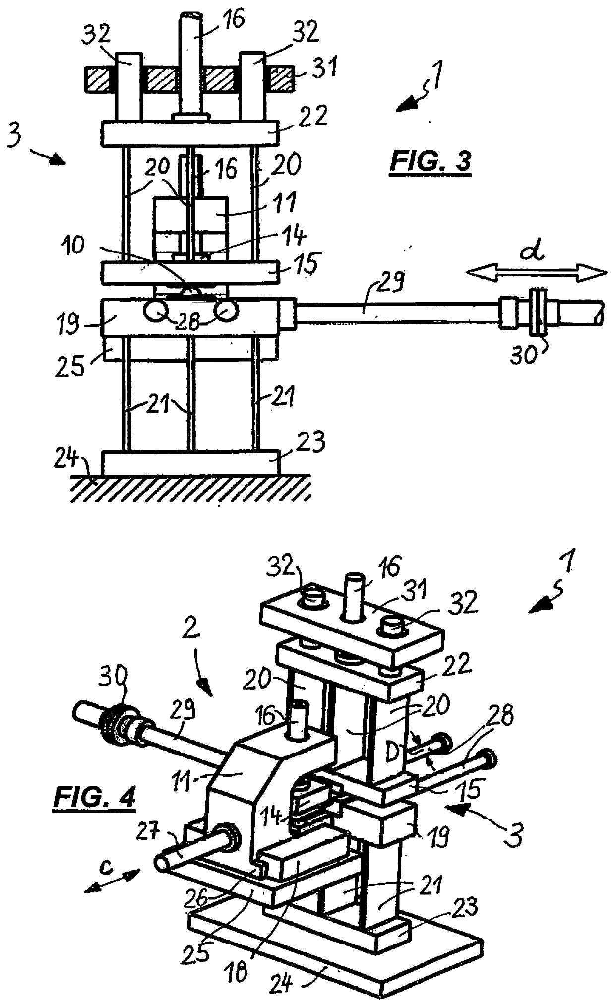
[0036]Shown in the figures is an embodiment of a linear friction welding machine according to the invention, specifically in a side view (FIG. 1), a front view (FIG. 3) and also in two perspective views which show the linear friction welding machine in two positions which are rotated anticlockwise by 90°.

[0037]In the figures, the same parts are also provided with the same designations.

[0038]First of all, the view of FIG. 1 may be dealt with, in which a linear friction welding machine 1, which comprises an upsetting unit 2 and also an oscillator unit 3, is shown in side view.

[0039]In this case, the upsetting unit 2 is provided with a clamping holder 4 and the oscillator unit 3 is provided with a clamping holder 5.

[0040]The clamping holder 4 comprises a lower holder part 6 and the clamping holder 5 comprises a lower holder part 8, in which in each case a workpiece 10 which is to be welded is inserted, wherein each of the inserted workpieces 10, by its side facing the workpiece 10 in t...


PUM

PropertyMeasurementUnit
Pressureaaaaaaaaaa
Pressureaaaaaaaaaa
Lengthaaaaaaaaaa

Abstract

A linear friction welding machine comprising a compression unit and an oscillator unit, each having a clamping holder for a workpiece. Both clamping holders are configured such that workpieces are held with the surfaces thereof to be welded, aligned and facing each other. The clamping holder of the compression unit is linearly movable relative to the clamping holder of the oscillator unit, and the latter is movable in an oscillating manner at right angles transversely with respect to the direction of travel of the compression unit and fixed to ends of vertical and horizontal supports which can be deflected laterally in a sprung manner in the oscillation direction, the other ends of which are anchored rigidly on supporting bodies. The supports are flexible under deflection in the oscillation direction but are designed to resist buckling when the clamping holders are loaded in the direction of travel of the compression unit.

Description

PRIORITY CLAIM[0001]The present application is a National Phase entry of PCT Application No. PCT / EP2016 / 079788, filed Dec. 5, 2016, which claims priority from German Patent Application Number 102015122314.7, filed Dec. 18, 2015, the disclosures of which are hereby incorporated by reference herein in their entirety.FIELD OF THE INVENTION[0002]The invention relates to a linear friction welding machine which allow the welding of two workpieces to each other by means of the welding method of linear friction welding.BACKGROUND OF THE INVENTION[0003]Friction welding methods, which were first developed over the course of past 50 years or so, are based on the principle that two pressed together surfaces which are to be welded and which execute a relative movement to each other are heated increasingly as a result of the friction which occurs in the process, wherein upon reaching a sufficient degree of heating of these surfaces the local pressure buildup which is required for achieving a weld...

Claims


Application Information

Patent Timeline
IPC IPC(8): B23K20/12B29C65/06B29C65/78B29C65/00
CPCB29C65/0618B29C66/83221B29C66/8242B29C66/1142B23K20/121B23K20/1205B29C65/7841B23K20/10B29C66/5261
Inventor FUCHS, FRANZ
Owner PEWAG AUSTRIA
Learn More