
Application method of the thermal error-temperature loop in the spindle of a CNC machine tool

a technology of cnc machine tools and thermal error temperature loops, which is applied in the direction of electric programme control, program control, instruments, etc., can solve the problems of insufficient in-depth analysis of the thermal deformation mechanism of the spindle and the thermal error of the spindl

Active Publication Date: 2020-08-27
DALIAN UNIV OF TECH
View PDF0 Cites 4 Cited by
  • Summary
  • Abstract
  • Description
  • Claims
  • Application Information

AI Technical Summary

Benefits of technology

The invention provides a way to investigate and analyze the way a spindle (a part of a machine) heats up and deforms. This information helps to design the machine in a way that reduces costs and improves efficiency. It also helps to develop a more accurate and robust method for compensating for the heat-related errors that occur in the machine.

Problems solved by technology

(1) At present, most of analyses on the thermal deformation mechanism of the spindle are carried out by the finite element method. The numerical method is based on the simulation and has a certain gap with the actual process.
(2) At present, the thermal error of the spindle can be obtained from the thermal deformation and temperature data. However, there is no method for the in-depth analysis of the spindle's thermal deformation mechanism.

Method used


Image

  • Application method of the thermal error-temperature loop in the spindle of a CNC machine tool
  • Application method of the thermal error-temperature loop in the spindle of a CNC machine tool

Examples


Embodiment Construction

[0025]In order to make the objects, technical solutions and advantages of the proposed invention more clear, a specific embodiment of the invention with the reference to a certain type of the vertical machining center is described as below.

[0026](1) The temperature sensors entitled by T1 and T2 are arranged on the upper and lower surfaces of the spindle box, respectively.

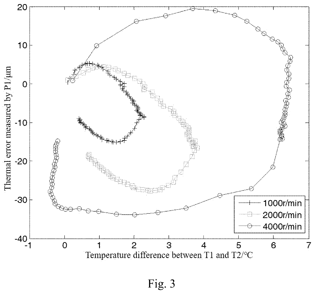
[0027](2) A bar and two displacement sensors are utilized to determine the thermal drift error along the X- and Y-directions of the spindle. The spindle continuously rotates at 2000 rpm for 1 hour during the test. It is found that the thermal drift errors in the X- and Y-directions are 1.2 μm and 8.2 μm, respectively. Therefore, it is concluded that the radial error along the Y-direction is the governing error. Moreover, after shutting down the machine for 3 hours, the Lion spindle error analyzer is used to test the radial thermal drift and thermal tilt error along the Y-direction of the spindle. The upper and lower...


PUM


Abstract

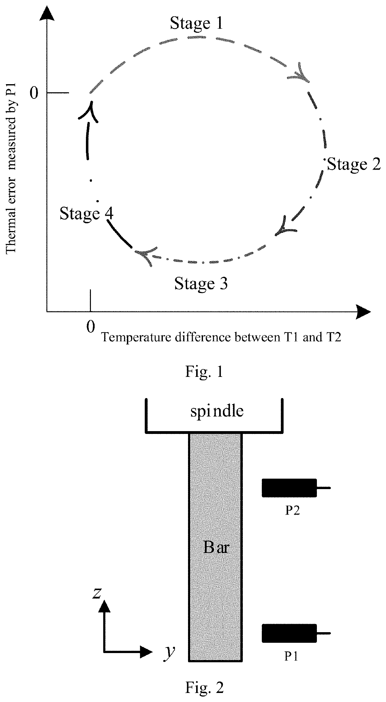
An application method of the thermal error-temperature loop in the spindle of a CNC machine tool. This uses a bar and two displacement sensors to determine radial thermal errors of the spindle. Meanwhile two temperature sensors are used to determine the temperature of the upper and lower surfaces of the spindle box. Then, the thermal error-temperature loop is drawn with the temperature difference between two temperature sensors as the abscissa and the radial thermal error of the spindle as the ordinate. Finally, the loop is employed to analyze the mechanism of the radial thermal deformation of the spindle and the thermal error level is evaluated. Since the method is based on measured data, the results of the analysis are closer to the reality, compared to those from the numerical simulations.

Description

TECHNICAL FIELD[0001]This invention belongs to the technical field of the thermal error testing of the CNC machine tools and specifically relates to an application method of the thermal error-temperature loop in the spindle of a CNC machine tool.BACKGROUND[0002]It was first found in Switzerland in 1933, through measuring and analyzing the coordinate-boring machine, that the thermal deformation is the main factor affecting the positioning accuracy of the CNC machine. Since then, many scholars have performed variety of researches on the thermal error mechanism and the machine accuracy.[0003]In the article Analysis on Thermal Dynamic Characteristics of CNC Machine Tool Spindle, which was published in the 9th issue of Journal of Tianjin University in 2013, Jiang et al confirmed the existence and variation of the thermal dynamic characteristics by using the finite element method and experimental research. In the article Thermal Characteristics Analysis and Experimental Study on High-Spee...

Claims


Application Information

Patent Timeline
Patent Type & Authority Applications(United States)
IPC IPC(8): G05B19/418
CPCG05B19/4184G05B2219/49207B23Q11/0003B23Q17/00B23Q17/22G05B19/401G05B2219/49209
Inventor LIU, KUOLIU, HAIBOLI, TELIU, HAININGWANG, YONGQINGJIA, ZHENYUAN
Owner DALIAN UNIV OF TECH
Learn More