Battery temperature raising device

a battery and temperature technology, applied in the direction of secondary cells, battery/fuel cell control arrangement, battery/hybrid vehicle, etc., can solve the problems of reducing the travelling distance determined by the motor, reducing the efficiency and deteriorating the electric power consumption. , to achieve the effect of efficient raising the temperature of the battery in charging and improving the electric power consumption

Active Publication Date: 2020-08-27
HONDA MOTOR CO LTD
View PDF0 Cites 5 Cited by
  • Summary
  • Abstract
  • Description
  • Claims
  • Application Information

AI Technical Summary

Benefits of technology

[0007]The disclosure provides a battery temperature raising device which efficiently raises the temperature of a battery in charging while utilizing heat of devices other than an electric heater as much as possible and can improve electric power consumption.

Problems solved by technology

It is known that the battery used for a hybrid vehicle, an electric vehicle, or the like has a reduced performance in a low temperature state.
Accordingly, charging time is increased and charging amount is decreased, and as a result, reduction of a travelling distance determined by the motor or deterioration of electric power consumption is caused.
That is, as long as the battery temperature is equal to or less than the predetermined temperature, the electric heater is driven regardless of temperature status or the like of other devices, and thus electric power is consumed excessively, resulting in a deterioration in electric power consumption.

Method used


Image

  • Battery temperature raising device
  • Battery temperature raising device
  • Battery temperature raising device

Examples


Embodiment Construction

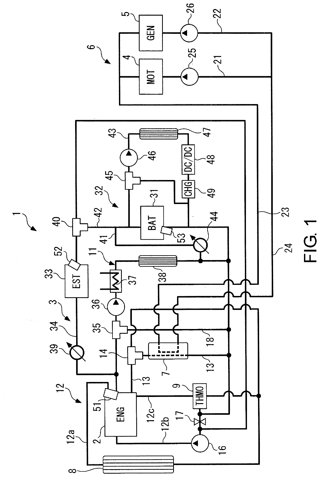
[0015]Exemplary embodiments of the disclosure are specifically described below with reference to the drawings. FIG. 1 schematically shows a cooling and temperature raising device for hybrid vehicle including a battery temperature raising device according to an embodiment of the disclosure.

[0016]As shown in the diagram, the hybrid vehicle (hereinafter, referred to as the “vehicle”) includes an internal combustion engine 2 and a motor 4 which are power sources, a generator 5 which converts mechanical power of the vehicle into electric power and generates the electric power, a chargeable / dischargeable battery (battery for short) 31 which is a power source of the motor 4, and the like.

[0017]A cooling and temperature raising device 1 performs cooling or temperature raising on the above-described devices or the like of the vehicle according to the status (hereinafter, the “cooling or temperature raising” is appropriately referred to as “the cooling, etc.”). The cooling and temperature rai...


PUM

PropertyMeasurementUnit
temperatureaaaaaaaaaa

Abstract

A battery temperature raising device is provided which raises, in a vehicle having an internal combustion engine and a motor using a chargeable battery as a power source, the temperature of the battery during charging in a state that the internal combustion engine is stopped. The battery temperature raising device includes a main circuit where cooling water circulates through the internal combustion engine; a first battery circuit connected in parallel to the main circuit; and a second flow rate control valve arranged in the first battery circuit. A first temperature raising control for raising the temperature of the battery is executed, when a battery temperature is equal to or below a predetermined temperature and an engine water temperature is higher than the battery temperature during charging the battery, by opening the second flow rate control valve and introducing the cooling water inside the main circuit into the first battery circuit.

Description

CROSS REFERENCE TO RELATED APPLICATIONS[0001]This application claims the priority benefit of Japanese Patent Application No. 2019-031871, filed on Feb. 25, 2019. The entirety of the above-mentioned patent application is hereby incorporated by reference herein and made a part of this specification.BACKGROUNDTechnical Field[0002]The disclosure relates to a battery temperature raising device which raises the temperature of a battery which is a power source of a motor equipped in a vehicle together with an internal combustion engine, and particularly relates to a battery temperature raising device which performs temperature raising during charging of a battery.Related Art[0003]It is known that the battery used for a hybrid vehicle, an electric vehicle, or the like has a reduced performance in a low temperature state. For example, if charging is performed in a low temperature state, charging efficiency is decreased. Accordingly, charging time is increased and charging amount is decreased...

Claims


Application Information

Patent Timeline
Patent Type & Authority Applications(United States)
IPC IPC(8): H01M10/615H01M10/625H01M10/6568H01M10/63H01M10/42
CPCH01M2010/4271H01M10/6568H01M10/625H01M10/63H01M10/425H01M10/615B60L58/27F01P3/12H01M10/633H01M10/663H01M2220/20Y02T10/7072Y02T90/14
Inventor TAKAZAWA, MASANOBUUTO, HAJIMETAKEDA, NAOAKITOYOKAWA, MASAYUKI
Owner HONDA MOTOR CO LTD
Why Eureka
Try Eureka