[0070]The present description is given in a non-limiting way, each characteristic of an embodiment being able to be combined with any other characteristic of any other embodiment in an advantageous way. In addition, each parameter of an example of realization can be utilized independently from the other parameters of said example of realization.
[0071]The meaning of the following terms is noted here:
[0072]“juxtaposed” means elements are placed side by side;
[0073]“in succession” and “successively” means one after the other; and
[0074]“linear” refers to the continuous aspect of a line.
[0075]It is now noted that the figures are not to scale.
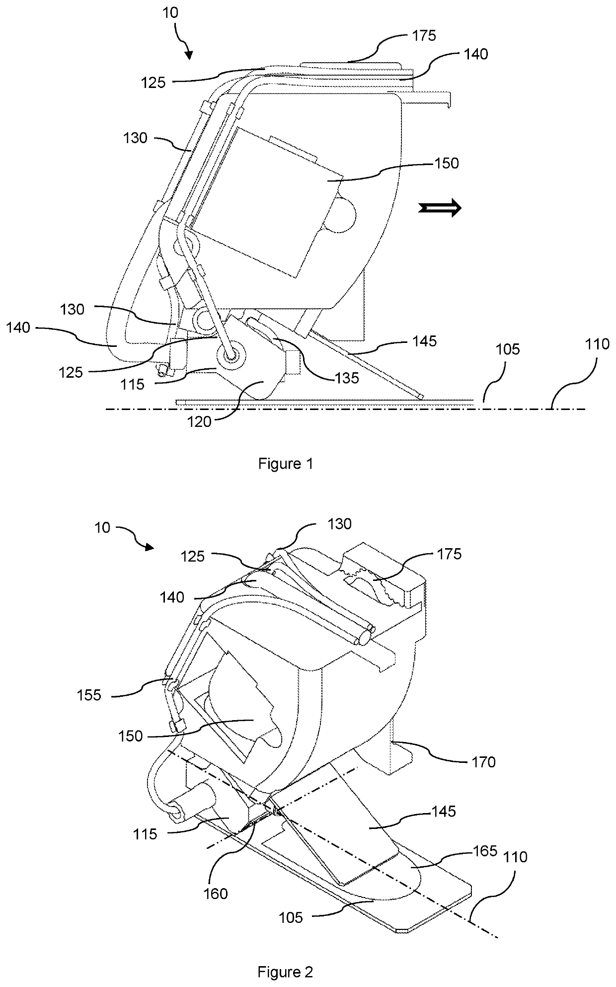
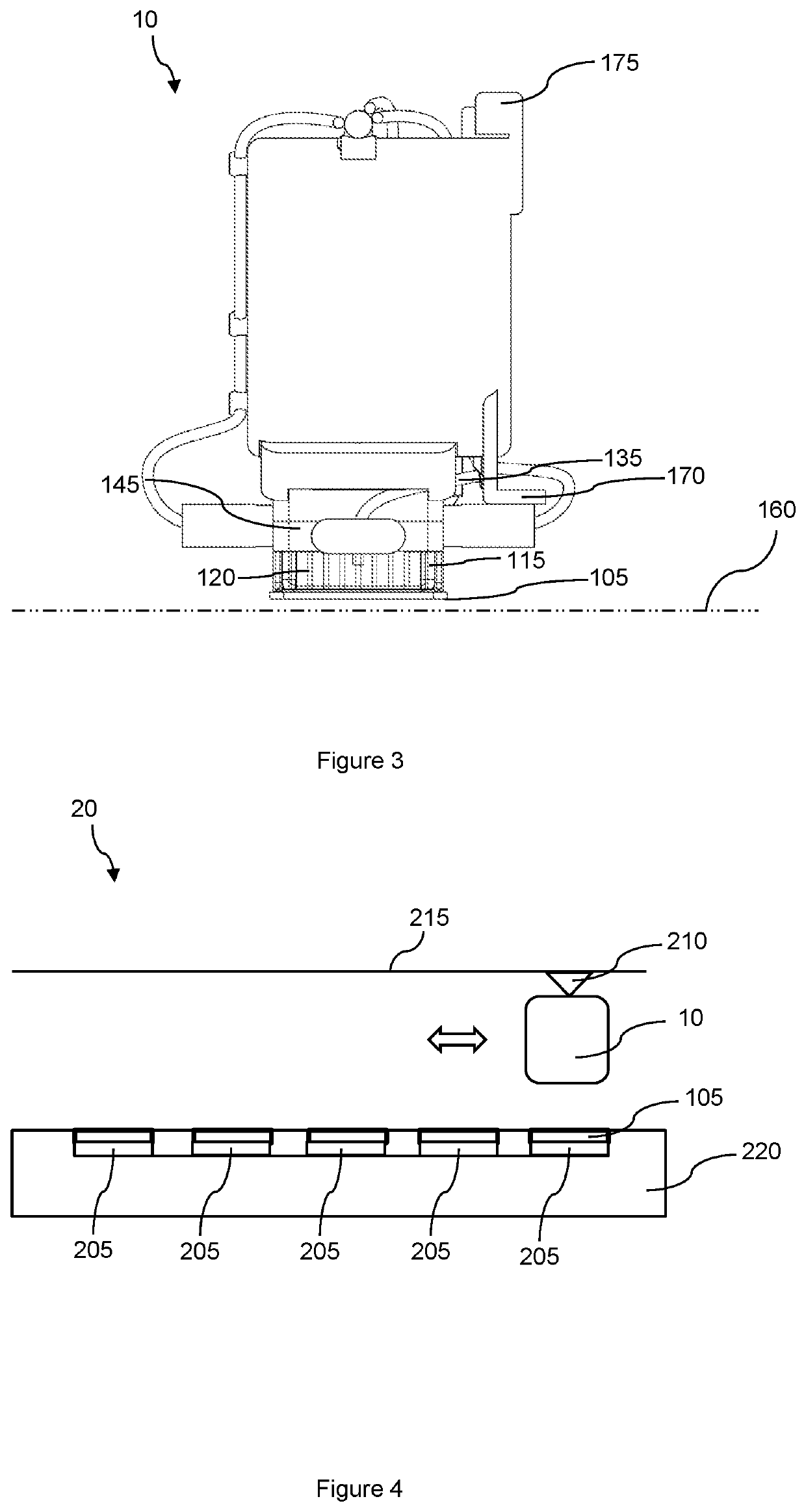
[0076]FIGS. 1 and 3 show several schematic views of an embodiment of the device 10 that is the subject of the present invention. The device 10 for staining an organic element on at least one slide 105 comprises a slide 105 support (not shown) on which is positioned the slide 105. The slide 105 defines an axis 110 contained within the plane of the slide 105.
[0077]For clarity, here, a slide for biomedical analyses is a thin, flat, rectangular piece of glass used as a support for medical analyses. The axis of the slide 105 is the axis passing via the middle of the rectangle of the slide 105 and parallel to the largest side of the rectangle. It is also noted that an organic element is body tissue, blood or any other sample taken from a living being.
[0078]The slide 105 support enables the slide to be placed in a horizontal position. In some embodiments, the slide 105 support keeps the slide in a horizontal position. The slide 105 support can be any means known to the person skilled in the art, fixed relative to the device 10.
[0079]In some embodiments, the organic element is positioned on the slide 105 before the slide 105 is placed on the support.
[0080]The device 10 also comprises a means 115 for spreading a staining fluid and/or a rinsing fluid on the slide 105, paired with a means 175 for relative displacement in translation in relation to the slide 105 along the axis 110 of the slide 105, the spreading means 115 having a linear element 120 extending along an axis 160 perpendicular to the axis 110 of the slide 105 and supplied with spreading fluid.
[0081]In some embodiments, the linear element 120 has at least two channels emerging close to the slide. The distance between the outlet of the channels 120 and the slide 105 is less than five millimeters. The channels are parallel to each other close to the slide such that each channel 120 delivers a similar amount of liquid. Preferably, the distance between the outlet of the channels 120 and the slide 105 is 0.3 millimeters.
[0082]In some embodiments, the linear element 120 has a slot. A slot is an aperture whose shape is contained within a rectangle and where the ratio of the large to small sides is greater than two. Preferably, the slot is rectangular and the dimension of the small side is equal to the dimension of a channel.
[0083]The linear element 120 is supplied by tubes 125, 130, 135 for delivering fluids, connected to tanks (not shown), each containing staining or rinsing fluid. A pump (not shown) handles the supply of fluid from the tank.
[0084]In the embodiment shown in FIGS. 1 to 3, the tube 135 is connected to a tank containing a rinsing fluid, and the tubes 125 and 130 are connected to tanks containing staining fluids. Preferably, all the tubes, 125, 130 and 135, emerge in the spreading means 115 in the middle of the distance between the channels 120 farthest apart, or in the middle of the slot, for example.
[0085]Preferably, the volume of a spread staining fluid and/or rinsing fluid is between 0.4 milliliters and 1 milliliter for a rectangular slide 105 of 25 millimeters by 75 millimeters.
[0086]In some embodiments, the spreading means 115 comprises two fluid supply means utilized simultaneously. A supply means comprises at least one tube, 125, 130 or 135, one pump and one tank. In these embodiments, two staining fluids reacting together to stain the organic fluid are mixed and delivered simultaneously. The tubes, 125 and 130, are supplied simultaneously with staining fluid. For example, one staining fluid is the Giemsa staining fluid and one staining fluid is a Giemsa diluent.
[0087]The supply means are activated simultaneously, for example after the command issued by the control means, and the two staining fluids are mixed at the entry of the channels 120 into the spreading means 115.
[0088]In some embodiments, the spreading means 115 comprises a means for mixing fluids coming from the supply means. The mixing means can be a screw or mixer or, when the spreading means and the suction means are combined, a spreading of the fluids mixed at the entry of the channels and then at least one suctioning of these fluids and another spreading of the suctioned fluids. More generally, the mixing means is configured to create a turbulent flow between the fluids to homogenize the mixture of the fluids.
[0089]In some embodiments, at least one tube 130 is attached to the spreading means 115 by tabs in the form of a deformable hook on a casing of the device 10. In some embodiments, at least one tube 125 is attached to the spreading means 115 by passing through the casing of the device 10.
[0090]The displacement means 175 can be a rack and a corresponding toothed wheel, or a pulley and belt assembly, in the axis 110 of the slide 105. Control of the displacement means 175 can be performed by a stepping motor.
[0091]The device 10 comprises a suction means 115 for suctioning the staining fluid and/or a rinsing fluid, paired with a means 175 for relative displacement in translation in relation to each slide 105 along the axis 110 of said slide 105.
[0092]Preferably, the suction means 115 comprises a linear element extending along an axis 160 perpendicular to the axis 110 of the slide 105 for carrying a suctioned fluid.
[0093]In some embodiments, the linear element 120 has at least two channels emerging close to the slide 105. The distance between the outlet of the channels 120 and the slide 105 is less than five millimeters. The channels are parallel to each other close to the slide such that each channel 120 suctions up a similar amount of liquid. Preferably, the distance between the outlet of the channels 120 and the slide 105 is 0.3 millimeters.
[0094]In some embodiments, the linear element 120 has a slot. A slot is an aperture whose shape is contained within a rectangle and where the ratio of the large to small sides is greater than two. Preferably, the slot is rectangular and the dimension of the small side is equal to the dimension of a channel.
[0095]The linear element 120 is connected to a suction tube 140 for suctioning waste fluids connected to a waste tank. A pump (not shown), for example managed by a control means, handles the suctioning up of fluids on a slide 105 towards the waste tank. Preferably, the tube 140 emerges in the suction means 115 in the middle of the distance between the channels 120 farthest apart, or in the middle of the slot, for example.
[0096]In some embodiments, the tube 140 is attached to the suction means 115 by tabs in the form of a deformable hook on a casing of the device 10. In some embodiments, the tube 140 is attached to the suction means 115 by passing through the casing of the device 10.
[0097]The displacement means 175 can be a rack and a corresponding toothed wheel, or a pulley and belt assembly, in the axis 110 of the slide 105. Control of the displacement means 175 can be performed by a stepping motor.
[0098]Preferably, the linear element 120 of the spreading means 115 is the linear element 120 of the suction means 115. This embodiment is represented in FIG. 1. In some embodiments, all the tubes, 125, 130, 135 and 140, emerge in the spreading means 115 in the middle of the distance between the channels 120 farthest apart, or in the middle of the slot, for example.
[0099]In some embodiments not shown in FIGS. 1 to 3, the suction means 115 is positioned in succession to the spreading means 115 along the axis 110 of the slide 105, the simultaneous utilization of the spreading means 115 and the suction means 115 creating a turbulent flow for cleaning the slide 105. In other words, the suction means is positioned in succession to the spreading means, and the device comprises a means for controlling the spreading means and suction means simultaneously, creating a turbulent flow for cleaning the slide. In these embodiments, a cleaning liquid is ejected by the spreading means 115 and immediately suctioned up by the suction means 115.
[0100]The suctioning by the suction means 115 simultaneously suctions up air and the liquid ejected, thus creating a mechanical friction between the cleaning liquid and the stained organic element. The impurities in the stained organic element are detached from the stained organic element and suctioned up with the cleaning liquid. The stained cells are held in place. The impurities are, for example, colorant precipitates formed during the spreading of the colorant.
[0101]Preferably, the distance between the linear element 120 of the spreading means 115 and the linear element 120 of the suction means 115 is less than two millimeters. And the linear elements 120 are parallel.
[0102]In some embodiments, for hematology, the device 10 also comprises:
[0103]at least one dispenser 170 of at least one drop of organic liquid on the slide placed on the support;
[0104]at least one smearing means 145 perpendicular to the axis 110 of the slide 105 smearing the organic liquid in the axis 110 of the slide 105; and
[0105]at least one means 150 for lifting a deactivated smearing means 145 in order to lower the smearing means 145 above the slide 105 to come into contact with the drop of organic liquid, which migrates by capillarity over the smearing means perpendicular to the axis 110 of the slide 105, the drop being smeared by relative displacement between the smearing means 145 and the slide 105.
[0106]The device 10 also comprises a distributor 170 distributing at least one drop of organic liquid on the slide 105. The distributor 170 can comprise a means for setting the organic liquid in rotation.
[0107]The smearing means 145 is preferably a rectangular slide in which the dimension of the smallest side is less than or equal to the dimension of the slide 105 perpendicular to the axis 110 of the slide 105. The slide of the smearing means 145 is inserted into a support comprising one portion made of a material sensitive to a magnetic force juxtaposed with a portion made of glass. The smearing means 145 comprises a means for setting in rotation relative to the casing of the device 10. The axis of rotation of the means for setting the smearing means 145 in rotation is perpendicular to the axis 110 of the slide 105. The axis of rotation is located at the junction of the portion made of a material sensitive to a magnetic force and the portion made of glass.
[0108]The lifting means 150 is an electromagnet located above the portion made of a material sensitive to a magnetic force. The electromagnet, once released, frees the portion of the slide of the smearing means 145 made of a material sensitive to a magnetic force, which causes the portion made of glass to be lowered towards the slide 105. The pressure exerted on the slide 105 by the smearing means 145 is provided by at least one spring.
[0109]Only the line segment 146 at the extremity of the portion of the slide made of glass is in contact with the slide 105. In this way, a drop of organic liquid placed on the axis 110 of the slide 105 is spread over the line segment 146 by capillarity when the line segment 146 comes into contact with the drop. Then, the drop spread in this way over the line segment 146 is driven by displacement of the lowered smearing means 145 along the axis 110 of the slide 105, and therefore smeared by capillarity. The line segment 146 forms an angle with the slide 105 such that only one edge of the parallelepiped formed by the slide of the smearing means 145 is in contact with the slide 105.
[0110]The displacement can be performed by a displacement means 175. The displacement means 175 can be a rack and a corresponding toothed wheel, or a pulley and belt assembly, in the axis 110 of the slide 105. Control of the displacement means 175 can be performed by a stepping motor.
[0111]In some embodiments, the spreading means 145 can be a slide lowered by translation. In some embodiments, the lifting means 150 can be any means for setting in rotation or in translation of an element known to the person skilled in the art.
[0112]In some embodiments, the device 10 comprises a tank 70 for cleaning the smearing means 145, into which the smearing means 145 is lowered to be cleaned. The cleaning tank is placed in the axis 110 of the slide 105. Once the drop has been smeared, the smearing means 145 is lifted and lowered again into the cleaning tank 70 to prevent any contamination of one organic fluid sample by another.
[0113]The cleaning tank 70 has the shape of a sloping chamfer or side of a triangle 705 and comprises, on one surface, a spreading means 710 and a suction means 710 similar to those described above, creating a turbulent flow as indicated above. The fluid used is an isotonic diluent. In other embodiments, the isotonic fluid is spread in the cleaning tank 70 and the cleaning is performed by immersion of the smearing means 145.
[0114]Preferably, the cleaning tank 70 comprises a drain 715 for cleaning fluid.
[0115]In FIGS. 1 to 3, the embodiment of the device 10 shown comprises the distributor at least one drop of organic liquid, the spreading means 115 and the suction means 115 whose channels 120 are combined, the lifting means 150 and the smearing means 145 grouped together in a casing. The means 175 for displacing the spreading means, suction means 115 and smearing means 145 are a single displacement means 175. The device 10, of FIGS. 1 to 3, is mounted on a chassis (not shown) comprising a slide 105 support fixed relative to the chassis. The displacement means 175 displace the device 10 relative to the chassis, along the axis 110 of said slide 105.
[0116]In other embodiments, the device 10 is fixed relative to the chassis and each slide 105 is mobile relative to the chassis. The displacement means 175 displaces each slide 105 relative to the chassis, along the axis 110 of said slide 105.
[0117]These embodiments make it possible to have a compact device 10 particularly suited to analysis laboratories carrying out a limited number of analyses every day.
[0118]The embodiments of the staining device, 20 and 30, shown in FIGS. 4 and 5, the device, 20 or 30, comprises at least two juxtaposed supports, 205 or 310, for slides 105 and means, 210 or 315, for relative displacement between the staining device and each slide, configured to position the staining device 10 along the axis 110 of each slide 105 in succession.
[0119]In FIG. 4, each slide support 205 keeps a slide 105 in a horizontal position in a rack 220. The axes 110 of the slides 105 are parallel. The displacement means 210 is a rack and a corresponding means or a pulley and belt assembly, in an axis perpendicular to the axis 215 of each slide 105. The displacement means 210 can be any means for displacement in translation known to the person skilled in the art. Control of the displacement means 210 can be performed by a stepping motor. In FIG. 4, the device 10 corresponds to the device 10 shown in FIGS. 1 to 3.
[0120]The device 10 performs a first pass for smearing the smear and several other passes, spaced by lengths of time controlled, for example by a control means, as a function of the contact times of the colorants, for the different colorants and rinse. In some embodiments, the device 10 also has means for homogenizing the tubes of blood, piercing the plug, taking a sample of the blood and forming a drop.
[0121]FIG. 5 shows a third particular embodiment of the device 30 that is the subject of the present invention. In the device 30, the various means carrying out the various functions are separated into at least two different modules of device 10. All the modules form the device that is the subject of the present invention.
[0122]In the embodiment shown, the modules are arranged in a circular arc and each slide is displaced relative to the modules along an axis corresponding to the radius of the circular arc that corresponds to a position of the axis 110 of a slide 105. The device 30 comprises several slide supports 310, and the slide supports 310 are arranged in a circle on a carousel having a circular disk shape 305. For clarity, here, a carousel is an appliance intended for transporting, in a closed circuit, loads, objects or goods.
[0123]The slides 105 are loaded onto the carousel 305 when the slide support 310 is situated at a first location, represented by an arrow towards the carousel 305 on the left of FIG. 5. The slide 105 is unloaded from the carousel 305 in a location other than the loading location, and before a complete rotation of the carousel 305. The loading and unloading of the slides can be automated.
[0124]The axis 110 of each slide 105 corresponds to a radius of the carousel. The circular arc between the axis 110 of each slide 105 is identical. The supports 310 for slide 105 are spread evenly on an upper surface of the carousel 305.
[0125]The carousel is considered to comprise n locations juxtaposed or side by side on the circular arc, each location forming a different radius. A module of the device 10 can be positioned opposite a location. A module can comprise:
[0126]a distributor 170 distributing at least one drop of organic liquid on a slide 105;
[0127]a means 115 for spreading a staining fluid;
[0128]a means 115 for spreading a rinsing fluid;
[0129]a spreading means 115 comprising two staining fluid supply means utilized simultaneously;
[0130]a suction means 115 different from each spreading means;
[0131]a spreading means 115 whose channels 120 are combined with the channels of a suction means 115;
[0132]a smearing means 145 and a lifting means 150;
[0133]a spreading means and a suction means positioned in succession, and the device comprises a means for controlling the spreading means and suction means simultaneously, creating a turbulent flow for cleaning the slide;
[0134]or a combination of the above means.
[0135]An example of the embodiment shown in FIG. 5 is described below.
[0136]The loading position contains a module comprising a distributor 170. The module in the next position comprises a smearing means 145 and a lifting means 150. The following module comprises a means 115 for spreading a staining fluid. The very next module comprises a means 115 for suctioning a staining fluid. The next module comprises a means 115 for spreading two staining fluids simultaneously. The following module comprises a means 115 for spreading a rinsing fluid. Lastly, the final module before unloading comprises a module 115 for suctioning the rinsing fluid.
[0137]The unloading location is shown by an arrow on the right of the device 30 of FIG. 5. The rotation of the carousel 305 can be punctuated by drying phases of a predetermined length. Preferably, to control the drying time for each staining phase, each spreading means 115 comprises channels 120 combined with a suction means. The suction means 115 of different modules can therefore be activated at different times depending on the drying or waiting times required for each colorant before a rotation of the carousel 305.
[0138]The carousel 305 can be paced to change position at a fixed frequency. The frequency can be between 30 and 60 seconds. The various modules are distributed on the periphery of the carousel 305, which comprises a number of locations. Preferably, the carousel comprises more than ten locations. Preferably, the carousel 305 comprises forty locations.
[0139]For example, in some embodiments: a first slide 105 is positioned on the carousel 305, the carousel 305 turns one position which makes it possible to place it in the smearing position and, possibly, to deposit another slide. The smear must dry several minutes before receiving a first colorant. Therefore the first staining module must be not be next but rather several positions further, based on the desired rotation rate and drying time.
[0140]In some embodiments, the device 30 is accompanied by a module comprising a conveyor in translation on which are positioned slides 105 along its axis 110. Each slide 105 is first positioned under a distributor, then under a smearing means 145, equipped with a lifting means 150, which is lowered while a drop is deposited onto a preceding slide. The translation of the conveyor thus spreads the organic liquid on the slide 105.
[0141]In this embodiment, the slides 105 are loaded on the carousel 305 impregnated with the dried organic liquid.
[0142]FIG. 6 shows a series of steps of method 60 for staining an organic material on at least one slide 105, said slide 105 defining an axis 110 contained within the plane of the slide 105, said method comprising the following steps:
[0143]positioning 61 at least one slide 105 on at least one support, 205 or 310, of the slide 105;
[0144]spreading 66 a staining fluid and/or a rinsing fluid on the slide 105 by means of a linear element 120 along an axis perpendicular to the axis 110 of the slide 105; and
[0145]suctioning 67 the staining fluid and/or a rinsing fluid by means of a linear element 120 along an axis 160 perpendicular to the axis 110 of the slide 105.
[0146]In some embodiments, the method 60 also comprises the following steps:
[0147]distributing 62 at least one drop of organic liquid on the slide 105;
[0148]lowering 63 a smearing means 145 above the slide 105;
[0149]smearing 64 the organic liquid along the axis 110 of the slide 105 by displacement between the smearing means 145 and the slide 105; and
[0150]lifting 65 the smearing means 145.
[0151]Preferably, the method 60 comprises a step of drying the organic liquid and/or a staining fluid. The drying step preferably occurs after each smearing step and after each spreading step. The drying step is shown by a stopwatch in FIG. 6.
[0152]The positioning step 61 can be manual, for example on a support 205 of FIG. 2, or automated, for example on a support 310 of device 30.
[0153]The distribution step 62 is carried out by a distributor 170. Preferably, the drop is distributed on the axis 110 of the slide 105. Preferably, the drop is distributed in an area of the slide 105 around the middle of the slide 105 along the axis 110 and whose dimension along the axis 110 of the slide 105 is less than seventy-five percent of the dimension of the slide 105. A drop has a volume of the order of five microliters.
[0154]The lowering step 63 is utilized by the lifting means 150. The smearing step 64 is performed by the lowered smearing means 145. The displacement of the smearing means 64 along the axis of the slide 105 is sufficient to smear the organic liquid by capillarity. The lifting step 65 is performed by activating the lifting means 150. The smearing means 145 is lifted to avoid interfering with the staining during the spreading step 66.
[0155]The lowering step 66 is utilized by the spreading means 115. During the spreading step 66, a staining fluid and/or a rinsing fluid can be spread. In some embodiments, the method 60 also comprises a step of supplying at least two fluids during the spreading step 66. The spreading 66 is therefore a simultaneous spreading of two staining fluids. The spreading step 66 can be preceded by a step of mixing two staining fluids. The spreading step 66 can be utilized simultaneously with a suction step 67.
[0156]The suction step 67 is utilized by the suction means 67.
[0157]The method 60 can comprise several repetitions of a spreading step 66 and suction step 67 pair.
[0158]In some embodiments, the method 60 also comprises a step of relative displacement between, a spreading step 66, a smearing step 64 and/or a suction step 67, along the axis 110 of one slide 105 to the axis 110 of another slide 105. Such relative displacements are described with reference to FIGS. 4 and 5, for example.
[0159]In some embodiments, the method 60 comprises the following prior steps:
[0160]mixing tubes of organic liquid by rotation; and
[0161]during the positioning step 61: [0162] piercing a plug of the tube by a needle; [0163] extracting a predefined amount of organic liquid; [0164] forming a drop of organic liquid at the end of a thin tube, known as a “pipette”, contained in the dispenser and emerging close to the slide.
[0165]In some embodiments, the method 60 comprises a step of cleaning the smearing means 145 by contact with the cleaning liquid.
[0166]Preferably, the method is utilized by one of the embodiments 10, 20 or 30 described above.
[0167]In the embodiments shown in FIGS. 1 to 5, a slide 105 is placed in a slide support 205 during the positioning step 61. Then a drop of organic liquid is distributed on the slide 105 by the distribution means during a distribution step 62. The line segment 146 of the smearing means 145 is placed opposite the drop then lowered during the lowering step 63. The lowering of the smearing means 145 by the lifting means 150 spreads the drop on the slide 105 by capillarity. Then the lowered smearing means 145 is displaced along the axis 110 of the slide 105 according to the smearing step 64. The smearing means 145 is then lifted during a lifting step.
[0168]The device 10 of a module of the device 10 or the slide 105 is displaced to put the spreading means 115 opposite the location where the drop of organic liquid has been deposited. The displacement can be along the axis of the slide 105 to a predefined location or under a different module. The spreading means 115 is supplied with at least one staining liquid and the device 10 is displaced along the axis 110 of the slide 105 in the same direction as the smearing direction when the staining liquid is injected and emerges from the linear element 120 during the spreading step 66.
[0169]Then, the device 10 of a module of the device 10 or the slide 105 is displaced to put the suction means 115 opposite the location where the drop of organic liquid has been deposited. The displacement can be along the axis of the slide 105 to a predefined location or under a different module. The suction means 115 is put into operation and the device 10 is displaced along the axis 110 of the slide 105 in the same direction as the smearing direction when the staining liquid is suctioned by a linear element 120 after a predefined length of time based on the staining liquid during the suction step 67.
[0170]The spreading step 66 and suction step 67 can be repeated several times with several different staining or rinsing fluids. The staining fluids can be mixed.
[0171]Preferably, the method 60 utilizes the functions of the device 10, 20 or 30.
[0172]As can be understood from reading the present description, the following means may also be called:
[0173]for a spreading means: a distributer, a distribution circuit or a spreader;
[0174]for a suction means: a suction unit, a suction circuit or a suction pump;
[0175]for a displacement means: a displacement motor;
[0176]for a mixing means: a blender or a mixer;
[0177]for a smearing means: a spreader or an applicator;
[0178]for a lifting means: lifter or hoist;
[0179]for a control means: controller;
[0180]for a means for setting in rotation: a rotation motor; and
[0181]for a supply means: a supply circuit or a supply pump.