Lower limb of an exoskeleton with low power consumption

a technology of exoskeleton and lower limb, which is applied in the field of lower limbs of ambulatory exoskeleton, can solve the problems of consuming a lot of power, weighing on the user, and the entire mass of the exoskeleton, so as to reduce the power consumption of an ambulatory exoskeleton and increase safety

Pending Publication Date: 2020-09-10
COMMISSARIAT A LENERGIE ATOMIQUE ET AUX ENERGIES ALTERNATIVES
View PDF0 Cites 3 Cited by
  • Summary
  • Abstract
  • Description
  • Claims
  • Application Information

AI Technical Summary

Benefits of technology

[0004]An object of the invention is to reduce the power consumption of an ambulatory exoskeleton and to increase safety in the event of a power failure or another software or hardware problem.SUMMARY OF THE INVENTION
[0007]The invention thus makes it possible to take up a load of unknown mass without the need to parameterize the lower limb, provided that this mass is less than the pretensioning force.
[0008]A particularly simple embodiment is obtained when the means for varying the distance separating the ends of the leg segment comprise a cable, which will advantageously be able to extend between the pelvis segment and the foot segment. The configuration is further simplified when the spring element is a leaf spring, it being possible for the leaf spring to perform the dual function of a spring element and of a structural component. The leaf spring can be positioned behind or in front of the leg of a user wearing the exoskeleton.
[0011]The variation of the distance separating the ends of the leg segment can then be directly controlled on the basis of the measurement output by this sensor, thus ensuring that the foot follows the leg of the user in the swing phase.

Problems solved by technology

Since the leg actuator takes up all of the load itself, it consumes a lot of power, including in static phases.
Finally, in the event of a power supply failure, the entire mass of the exoskeleton and its possible load will weigh on the user, which may be dangerous to the latter.

Method used


Image

  • Lower limb of an exoskeleton with low power consumption
  • Lower limb of an exoskeleton with low power consumption
  • Lower limb of an exoskeleton with low power consumption

Examples


second embodiment

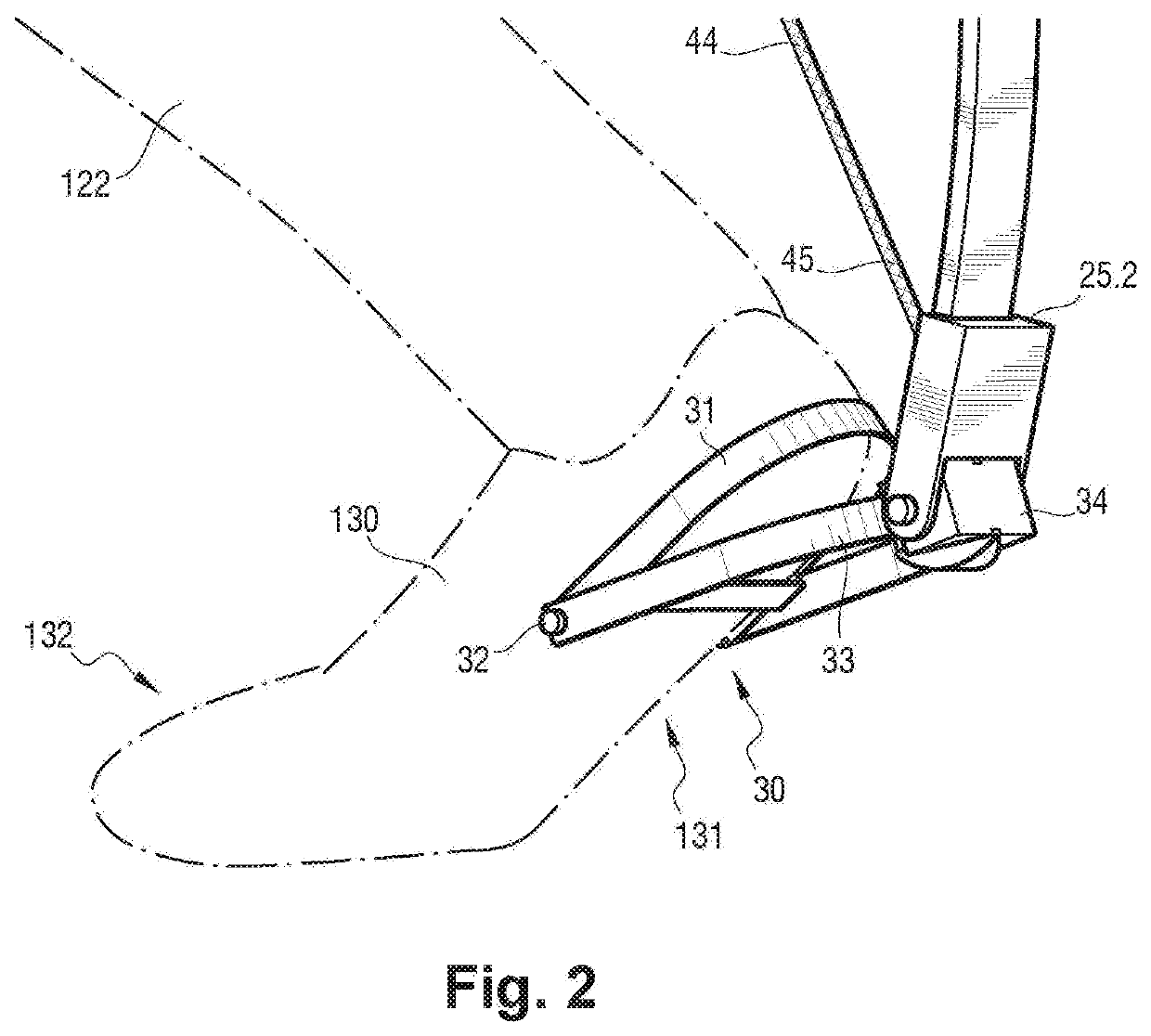
[0036]With reference to FIG. 4 and according to the invention, the foot segment 30 comprises a highly sensitive linear potentiometric sensor on the foot segment 30 of the exoskeleton 1 and connected to the unit 50.

[0037]This sensor 62 measures the distance that separates the first element 31 from the second element 32 of foot segment 30. From this distance it is possible to deduce the attitude (angular position and length) of the leg 122, hence the distance separating the pelvis segment 10 from the foot segment 30. The intention of the user 100 to leave the stance phase in order to walk is detected when the sensor 62 measures a movement. This measurement is transmitted to the unit 50, which then controls the geared motor 40.

[0038]This sensor 62 can also be composed of strain gauges in such a way as to measure the strain between the foot 30 and the ankle 25.2 (the distance d is then controlled on the basis of the strain measured, with a zero setpoint or with a slight offset).

third embodiment

[0039]With reference to FIG. 5 and according to the invention, the pelvis segment 10 comprises a ball-type slideway 70 oriented substantially vertically when the exoskeleton 1 rests on a horizontal ground surface. A first carriage 71 is mounted freely, or with a weight compensation spring, to slide on the slideway 70. The first carriage 71 carries the interface 60, to which the load 61 is connected, and also the geared motor 40, the pulley 43, its stop 46, the screw 12 and the bracket 14. Other elements of the pelvis segment 10 can also be carried by the first carriage 71, for example the command and control unit 50 and / or the electric accumulators 41.

[0040]The functioning of the exoskeleton 1 is identical to what has been described above. The set-up of the geared motor 40 and of the interface 60 for carrying the load 61 permits a free flexion travel of the legs (making it possible, for example, to crouch down) free, during which it is not necessary to adjust the geared motor 40, wh...

fourth embodiment

[0042]With reference to FIGS. 6 and 7 and according to the invention, the pelvis segment 10 comprises a ball-type slideway 73 oriented substantially vertically when the exoskeleton rests on a horizontal ground surface. A second carriage 74 is mounted to slide on the slideway 73. An electric actuator 75, connected electrically to the unit 50, extends between the pelvis segment 10 and the second carriage 74 in such a way that a retraction of the actuator 75 causes a translation of the second carriage 74, which moves the latter away from the first end 21 of the leg segment 20, which end 21 is articulated on the pelvis segment 10. As can be seen in FIG. 6, the first end 45 of the cable 44 is connected to the second end 25.2 of the leaf spring 25 and, as can be seen in FIG. 7, the second end 46 of the cable 44 is coupled to the pelvis segment 10, here to a point of the slideway 73. The second carriage 74 carries an idler pulley 76 about which the cable 44 winds. Thus, a movement of the s...


PUM


Abstract

A lower limb (1) of an ambulatory exoskeleton comprising at least a pelvis segment (10). a leg segment (20) and a foot segment (30), the leg segment (20) being hinged at the First end (21) of same to the pelvis segment (10) and at the second end (24) of same to the foot segment (30). the leg segment (20) comprising a spring element (25) and means (40. 44) for varying the distance (d) separating the ends (21. 24) of the leg segment (20), the means (40. 44) for varying the distance (d) separating the ends (21. 24) of the leg segment (20) being carried by the pelvis segment (10).

Description

FIELD OF THE INVENTION[0001]The invention relates to the field of exoskeletons and more particularly to the lower limbs of an ambulatory exoskeleton.BACKGROUND OF THE INVENTION[0002]Traditionally, a lower limb of an ambulatory exoskeleton comprises a pelvis segment, on which a first end of a leg segment is articulated about a hip, and a foot segment, which is articulated, by way of an ankle, on a second end of the leg segment. Control of the lower limb requires at least one actuator for driving the flexion of the leg segment during walking and for taking up the forces applied to the exoskeleton. The forces applied to the exoskeleton may be from several sources: a load applied to the exoskeleton (load-bearing exoskeleton), a partial substitution of the movements of the user (rehabilitation exoskeleton), and, generally, most of the actual weight of the exoskeleton.[0003]Since the leg actuator takes up all of the load itself, it consumes a lot of power, including in static phases. The ...

Claims


Application Information

Patent Timeline
Patent Type & Authority Applications(United States)
IPC IPC(8): A61H3/00A61H1/02B25J9/00B25J9/10
CPCB25J9/0006A61H3/00A61H1/0262B25J9/104A61H2201/5064A61H2201/5069A61H2201/165A61H2201/0196A61H2001/027A61H2201/0192A61H2203/0406A61H2205/10
Inventor GEFFARD, FRANCKPONSORT, DOMINIQUE
Owner COMMISSARIAT A LENERGIE ATOMIQUE ET AUX ENERGIES ALTERNATIVES
Why Eureka
Try Eureka