Eureka AIR delivers breakthrough ideas for toughest innovation challenges, trusted by R&D personnel around the world.

Regenerative Braking Energy Dissipater And System And Method Of Using Same

Active Publication Date: 2020-09-10
MSNS LLC
View PDF0 Cites 0 Cited by
  • Summary
  • Abstract
  • Description
  • Claims
  • Application Information

AI Technical Summary

Benefits of technology

The patent is for a system that can collect energy from a regenerative braking system without using the battery. It also helps to dissipate the excess energy created from the regenerative braking system.

Problems solved by technology

Urban drive cycles have a considerable amount of acceleration and decelerating periods due to traffic control systems in place around towns and cities, and therefore, when decelerating, significant energy is lost.
Similarly, off road cycles also have a considerable need for acceleration and deceleration due to climbing and descending hills.
A drawback with regenerative braking is that under some operating scenarios the battery may not be able to accept more energy.
For example, if the battery is fully charged and yet the user desires to brake further, the system may not be able to accommodate this desire.
This is not a good solution because it is important to have consistent braking.
Further, it may be quite difficult to implement this switchover.
Such a system does not offer the possibility of switching back to the mechanical brakes should circumstances call for it.

Method used


Image

  • Regenerative Braking Energy Dissipater And System And Method Of Using Same
  • Regenerative Braking Energy Dissipater And System And Method Of Using Same
  • Regenerative Braking Energy Dissipater And System And Method Of Using Same

Examples


Embodiment Construction

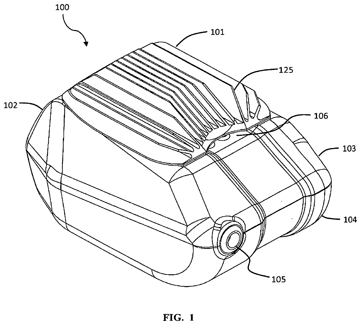
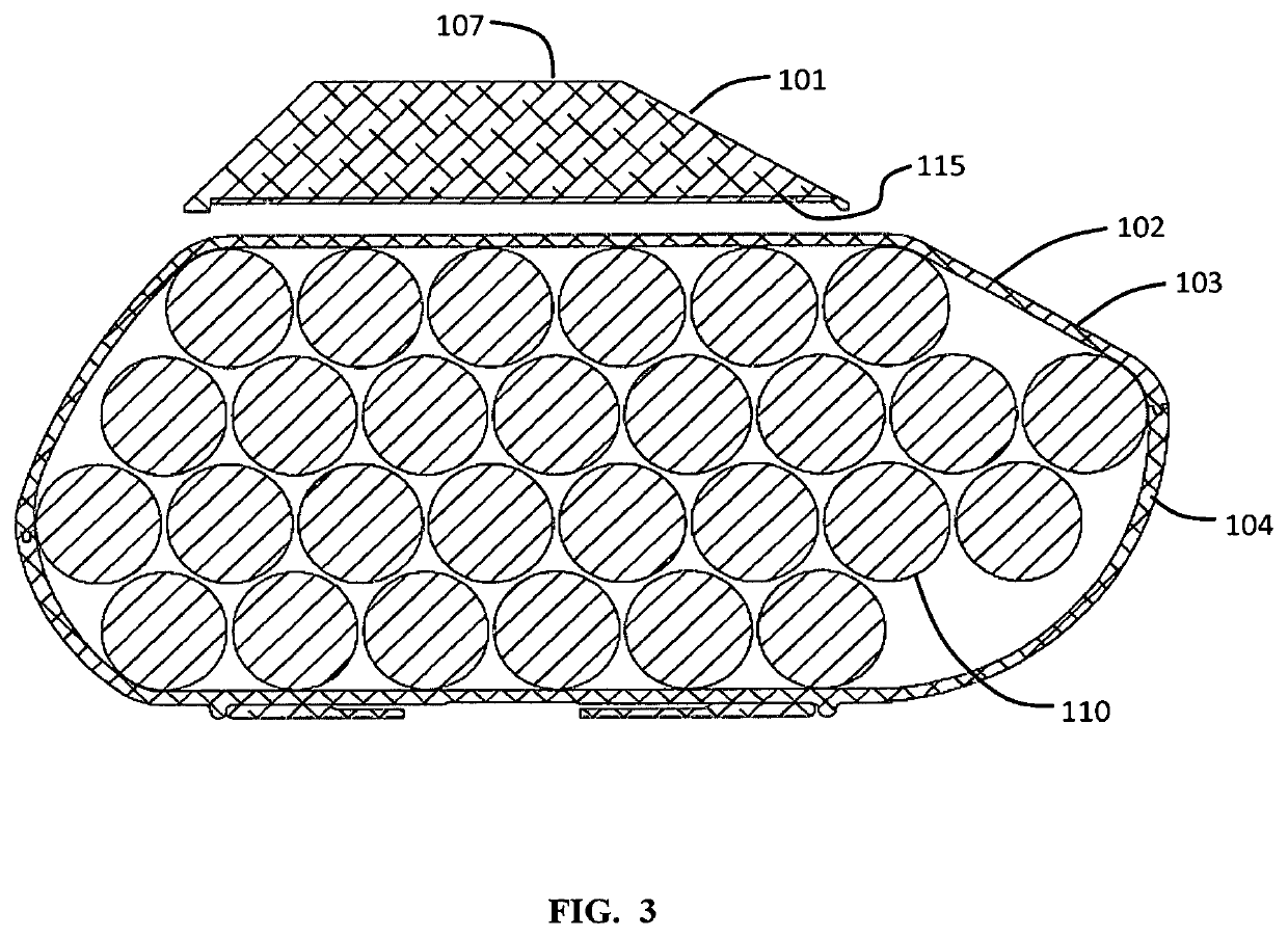
[0019]In some embodiments of the present invention, as seen in FIG. 1, a regenerative braking energy dissipater system 100 has a battery case 102 and a dissipater 101. The energy dissipater system may have an electronics portion within the battery case 102 which may direct input energy either to the battery or to the dissipater 101. The battery case 102 may have an upper case portion 103 and a lower case portion 104. The battery case 102 may have a charging interface receptacle 105 adapted to receive power for the charging of the battery or batteries. An airflow passage 106 allows for airflow underneath the dissipater 101.

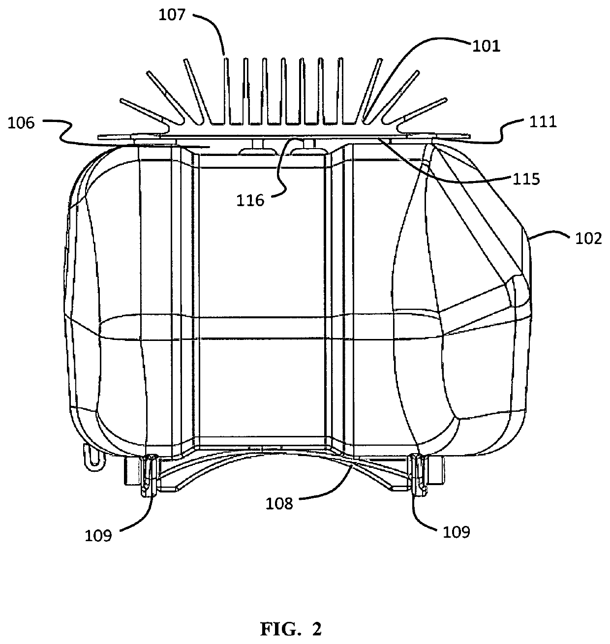
[0020]As seen in FIG. 2, the dissipater 101 may include a baseplate 115 and have fins 107 adapted for convective cooling of the dissipater. The baseplate 115 of the dissipater 101 may be electrically coupled to the battery case 102 with coupling pins 116. The baseplate 115 is also fastened to the battery case 102 with adhering portions 111. The adhering portions 11...


PUM


Abstract

A regenerative braking energy dissipater system which is adapted to dissipate energy from a regenerative brake in the case when the battery cannot accept further energy. The system may switch the energy flow from the battery to a dissipater when the battery has reached a high level of charge. The dissipater may include load resistors. The system may be designed such that the airflow around the dissipater flows over and under the dissipating plate.

Description

CROSS-REFERENCE TO RELATED APPLICATIONS[0001]This application claims priority to U.S. Provisional Patent Application No. 62 / 785,263 to Saiki, filed Dec. 27, 2018, which is hereby incorporated by reference in its entirety. This application claims priority to U.S. Provisional Patent Application No. 62 / 849,412 to Saiki, filed May 17, 2019, which is hereby incorporated by reference in its entirety.BACKGROUNDField of the Invention[0002]The present invention relates to electric transport, and more specifically to a regenerative braking energy dissipater system.Description of Related Art[0003]Motivated by the environmental, public health, ecological, and carbon-footprint issues associated with gasoline-powered automobiles, researchers, governments, and society as a whole have been engaged in a search for viable alternatives. Electric bicycles (e-bikes), which are propelled by a combination of pedaling and battery-powered electric motors, are a promising alternative to automobile transporta...

Claims


Application Information

Patent Timeline
IPC IPC(8): B60L7/22B60L58/26B60L50/60
CPCB60L7/22B60L50/60B60L2200/12B60L58/26B62M6/80H02P3/14B60L7/02B60L50/20B60L50/64B62M6/90B62J50/30B62J43/13Y02T10/64Y02T10/70B62M6/45
Inventor SAIKI, NEAL
Owner MSNS LLC
Why Eureka
Eureka Blog
Learn More