Apparatus for Measuring a Fluid Jet Guiding a Laser Beam

Pending Publication Date: 2020-09-24
SYNOVA SA
View PDF1 Cites 0 Cited by
  • Summary
  • Abstract
  • Description
  • Claims
  • Application Information

AI Technical Summary

Benefits of technology

The patent describes a system that uses secondary radiation to detect the presence of a laminar fluid jet. This radiation is only generated in a fluid jet and not in other forms of fluid. The system can accurately determine the length of the usable fluid jet and the characteristics of the flow. The system measures the distance of the fluid jet from a known reference point, and by using multiple detection signals at different positions along the fluid jet, the method allows for precise measurement of the usable fluid jet length. The system is easy to implement and process the results quickly.

Problems solved by technology

A problem typically encountered in the conventional apparatus is that the fluid jet is only laminar over a certain absolute length from the fluid jet generation nozzle.
Once the fluid jet becomes instable, the fluid is not anymore able to guide the laser beam such that the workpiece can be machined efficiently.
If the usable length of the fluid jet becomes too short, an efficient machining process may thus not be possible.
Further, a very short fluid jet, or the complete absence of a fluid jet, may indicate a graver problem with the apparatus, for instance a broken fluid jet generation nozzle.
Unfortunately, the conventional apparatus does not allow any inherent measurement of the usable length of the fluid jet.
External measuring devices could be used, but are typically inefficient since not being specifically designed for the case at hand, namely for measuring a high-intensity laser beam coupled into a very thin fluid jet (15-500 μm).
In particular, neither a complicated measuring setup should be necessary, nor should a post-processing of the measurement results require much time and computational resources.

Method used


Image

  • Apparatus for Measuring a Fluid Jet Guiding a Laser Beam
  • Apparatus for Measuring a Fluid Jet Guiding a Laser Beam
  • Apparatus for Measuring a Fluid Jet Guiding a Laser Beam

Examples


Embodiment Construction

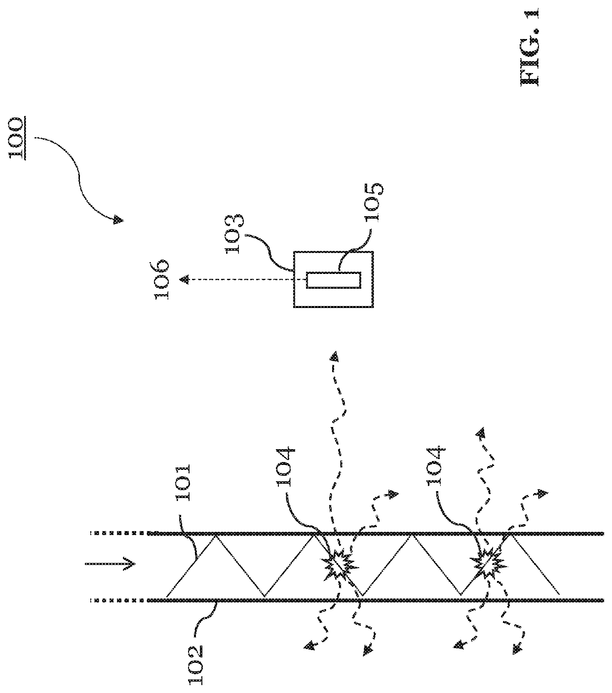
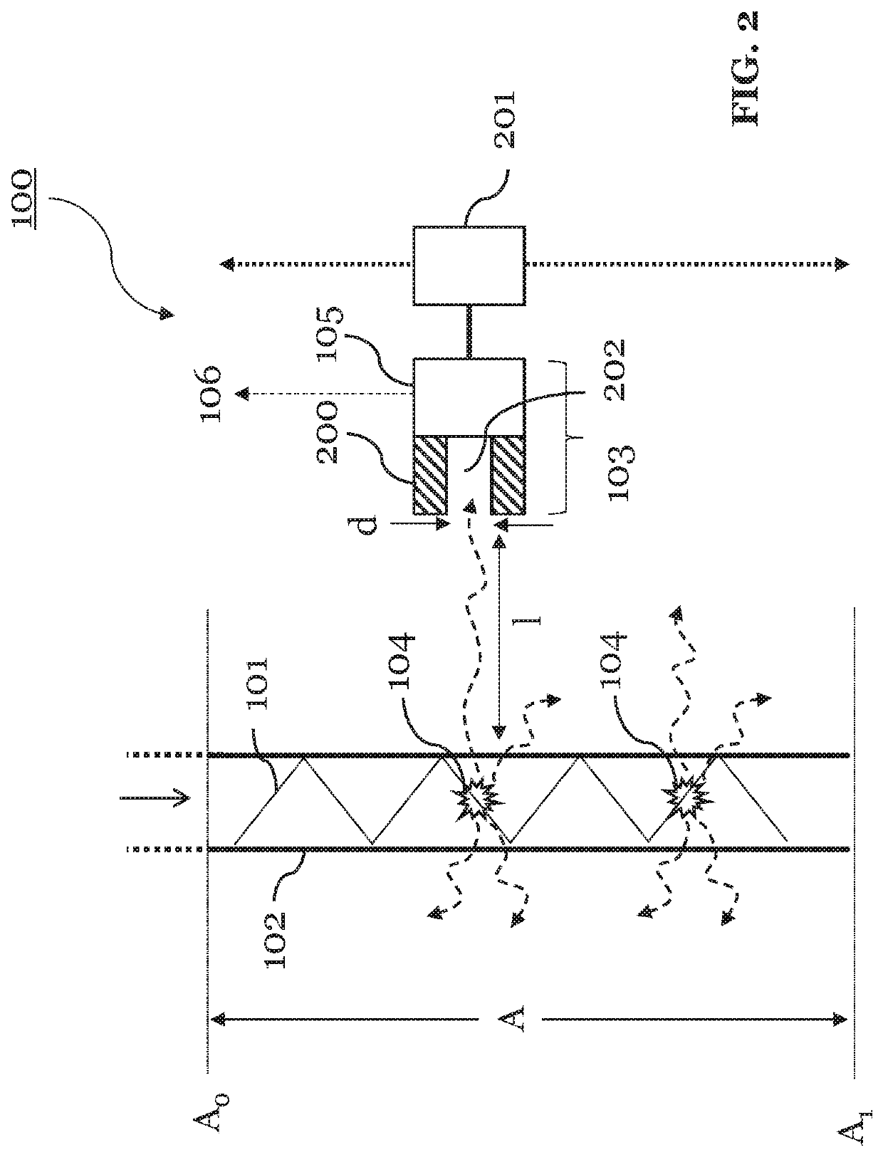
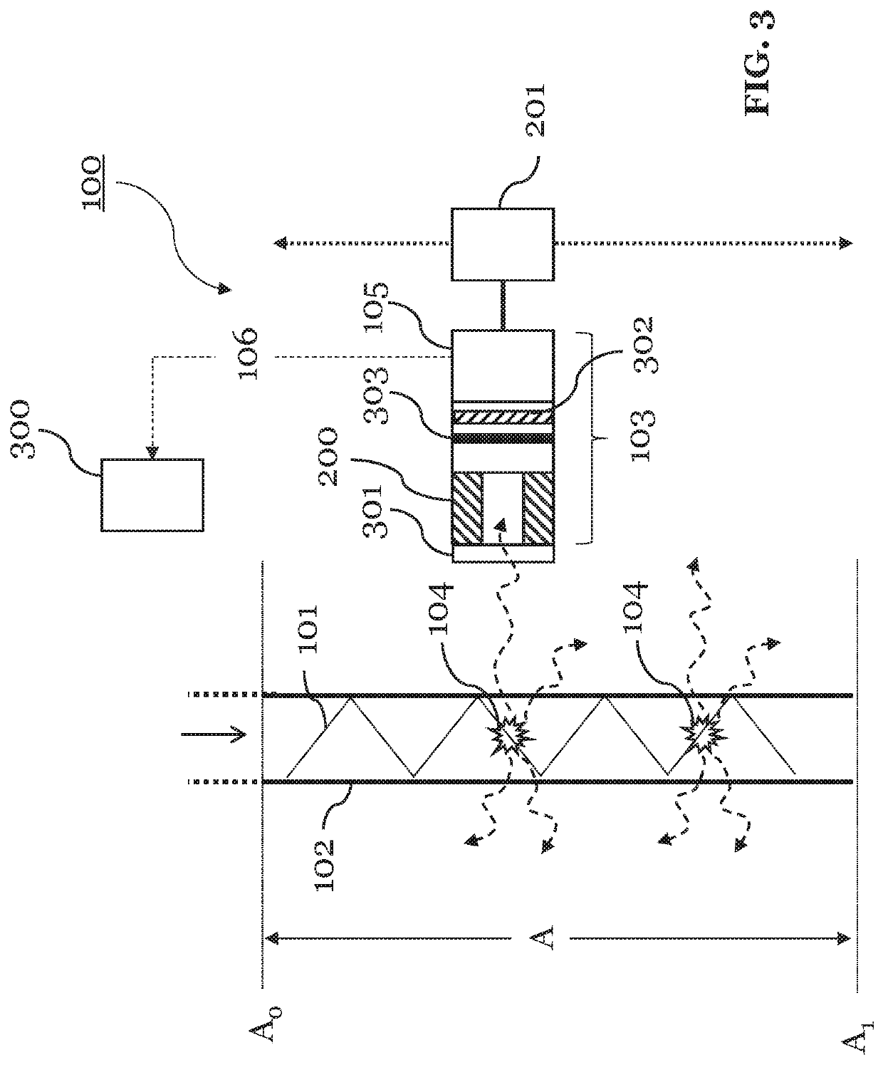
[0086]FIG. 1 shows an apparatus 100 according to an embodiment of the present invention. The apparatus 100 is configured to machine a workpiece with a high-intensity laser beam 101 coupled into a pressurized fluid jet 102. To this end, the apparatus 100 is configured to provide the fluid jet 102, and to couple the laser beam 101 into the fluid jet 102. The laser beam 101 may be pulsed or continuous. During the machining process, the workpiece may be positioned on a machining surface, which may or may not be part of the apparatus 100. In either case, the apparatus 100 can be arranged such that it is able to machine the workpiece disposed on the machining surface. The apparatus 100 may thereby control movements of the machining surface in up to three dimensions.

[0087]However, the apparatus 100 of the invention is particularly for measuring the fluid jet 102 guiding the laser beam 101. Accordingly, the components of the apparatus 100 required for this purpose are shown in FIG. 0.1. In ...


PUM

PropertyMeasurementUnit
Fractionaaaaaaaaaa
Fractionaaaaaaaaaa
Fractionaaaaaaaaaa

Abstract

The invention relates to an apparatus 100 for machining a workpiece with a high-intensity laser beam 101, the apparatus 100 being configured to provide a pressurized fluid jet 102 and to couple the laser beam 101 into the fluid jet 102. The apparatus 100 comprises a detection unit 103 configured to receive and detect secondary radiation 104 generated by the laser beam 101 in the fluid jet 102. The detection unit 103 includes a sensing unit 105 configured to convert secondary radiation 104 into a detection signal 106. The apparatus 100 is configured to generate, with the detection unit 103, a plurality of detection signals 106 at a single position or at different positions along the fluid jet 102.

Description

TECHNICAL FIELD[0001]The present invention relates to an apparatus for machining a workpiece with a high-intensity laser beam coupled into a pressurized fluid jet. According to the invention, the apparatus is particularly configured to measure the fluid jet guiding the laser beam. The invention relates also to a method for measuring a fluid jet guiding a high-intensity laser beam, wherein the laser beam is suitable for machining a workpiece. The invention is specifically concerned with measuring a length and / or flow characteristics of the fluid jet based on a laser-induced secondary emission.BACKGROUND[0002]A conventional apparatus for machining a workpiece with a laser beam coupled into a pressurized fluid jet is generally known. In order to machine the workpiece with the laser beam, the fluid jet is usually generated with a fluid jet generation nozzle, and the laser beam is coupled into and guided in the fluid jet onto the workpiece by means of total internal reflection.[0003]A pr...

Claims


Application Information

Patent Timeline
IPC IPC(8): B23K26/146B23K26/70
CPCB23K26/705B23K26/146B23K26/03
Inventor DIBOINE, JÉRÉMIEHIPPERT, DAVIDRICHERZHAGEN, BERNOLD
Owner SYNOVA SA
Why Eureka
Try Eureka