Eureka AIR delivers breakthrough ideas for toughest innovation challenges, trusted by R&D personnel around the world.

Pumping system and method for 3D printing

a printing system and 3d printing technology, applied in the direction of additive manufacturing processes, manufacturing tools, applying layer means, etc., can solve the problems of difficult, if not impossible, to use the conventional dispensing system used for epoxy and urethane thermoset resins, and achieve easy dispensing and mixing, suitable results, and varying viscosity

Active Publication Date: 2020-09-24
MAGNUM VENUS PROD
View PDF0 Cites 2 Cited by
  • Summary
  • Abstract
  • Description
  • Claims
  • Application Information

AI Technical Summary

Benefits of technology

The patent text describes the challenge of using polyester or vinyl ester resins for 3D printing applications because they are expensive and difficult to properly mix and meter. The curing of these resins requires a catalyst initiator, but using conventional dispensing systems for epoxy and urethane thermoset resins is difficult because of the widely varying viscosities and flow rates of the components. The patent aims to develop a 3D printing system that can effectively dispense polyester or vinyl ester resins and catalyst to a substrate without requiring excessive machining of the cured thermoset resin composition.

Problems solved by technology

However, the epoxy and urethane resins systems are relatively more expensive than polyester and vinyl ester resins.
However, the challenge of using polyester or vinyl ester resin systems for 3D printing applications is to properly mix and meter the components to achieve suitable curing of the resins.
The components of such a 3D printing system have widely varying viscosities and flow rates making it difficult, if not impossible to use the conventional dispensing systems used for epoxy and urethane thermoset resins.

Method used


Image

  • Pumping system and method for 3D printing
  • Pumping system and method for 3D printing
  • Pumping system and method for 3D printing

Examples


Embodiment Construction

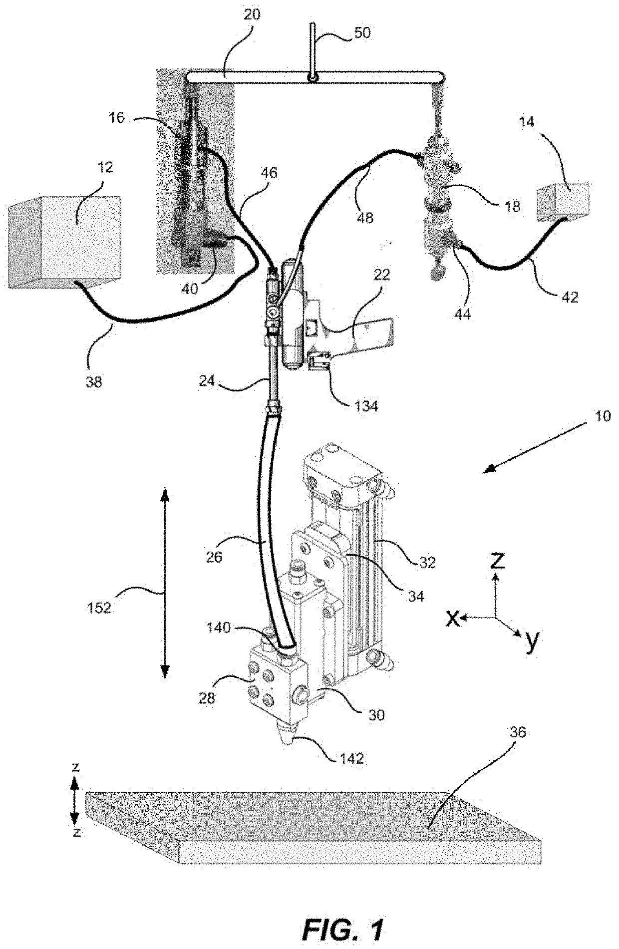
[0024]With reference to FIG. 1, there is shown an overall illustration of the three-dimensional (3D) printing system 10 according to the disclosure. The main components of the system 10 include a resin supply 12, a catalyst supply 14, a resin pump 16, a catalyst pump 18, pump linkage 20, a dispense gun 22, a mixer 24 attached to the dispense gun, a flexible hose 26 from the dispense gun 22 to a rotary dispense valve 28, an actuator 30 for the rotary dispense valve 28, a rodless slide 32, a slide plate 34 for the rotary slide actuator 30 on the rodless slide 32 and a movable table 36 for supporting and moving a substrate in a z direction for deposition of a 3D object thereon from the 3D system 10.

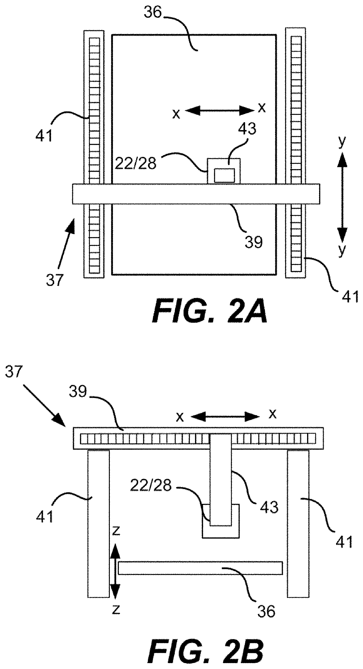
[0025]The dispense gun 22 and rotary dispense valve 28 are mounted on a gantry 37 as illustrated schematically in FIGS. 2A and 2B. The gantry 37 includes a movable top rail 39 that moves in an y direction along rails 41 and a support arm 43 for the dispense gun 22 and rotary dispense valve 2...


PUM

PropertyMeasurementUnit
volume ratioaaaaaaaaaa

Abstract

A three-dimensional (3D) printing system and method for printing with the 3D system. The 3D system includes a pneumatic dispense gun for mixing a thermoset resin and catalyst and dispensing a catalyzed resin to a rotary dispense valve for application of the catalyzed resin to a substrate on a movable table. The dispense gun contains a catalyst injection unit and a mixer for mixing the catalyst with the thermoset resin. The mixer is downstream of the catalyst injection unit and the catalyst injection unit includes a catalyst injector and a distribution ring surrounding the catalyst injector. One or more first pumps are provided for pumping the thermoset resin from a storage container to the pneumatic dispense gun. A second pump is provided for pumping the catalyst from a storage container to the dispense gun.

Description

TECHNICAL FIELD[0001]The disclosure is directed to a three-dimensional (3D) printing system and a method for 3D printing, and in particular to a 3D printing system and method for printing with a thermoset resin material and catalyst.BACKGROUND AND SUMMARY[0002]Polyester and vinyl ester putties have been available to the fiberglass reinforced plastics (FRP) industry for a number of years. The fillers used in these resins are wide ranging, common fillers, including fumed silica, calcium carbonate, glass and plastic micro bubbles to name a few.[0003]Polyester and vinyl ester materials are typically used in two processes. The majority of the processes use the foregoing material for bonding (gluing) applications where the putty is applied to a cured laminate, and a second laminate or core is then pressed into the putty until the putty is cured. The other process uses the foregoing material to manufacture FRP tooling or molds. The putty is applied to a frame work and cured. Once the putty...

Claims


Application Information

Patent Timeline
Patent Type & Authority Applications(United States)
IPC IPC(8): B29C64/321B33Y10/00B33Y30/00B29C64/106B29C64/209B29C64/314B33Y40/00B33Y70/00
CPCB29C64/321B29C64/314B33Y70/00B29K2067/00B29K2031/00B33Y40/00B33Y10/00B29C64/209B33Y30/00B29K2105/0014B29C64/106B29C48/05B29C48/266B29C48/29B29C48/365B29C64/336B29B7/7447B29B7/325B05B7/0408B05B7/1209B05B13/041B29B7/7457B29B7/748
Inventor WALCH, MICHAEL D.DELUCA, TIMOTHY G.
Owner MAGNUM VENUS PROD
Why Eureka
Eureka Blog
Learn More