Hydraulic cylinder

a technology of hydraulic cylinders and cylinder bodies, which is applied in the direction of fluid-pressure actuators, etc., can solve the problems of unfavorable change of distance between magnetic sensors and non-ring-shaped magnets, etc., and achieves the reduction of axial dimension of piston bodies, the effect of simplifying the structure and reducing the weight of products

Active Publication Date: 2020-09-24
SMC CORP
View PDF0 Cites 7 Cited by
  • Summary
  • Abstract
  • Description
  • Claims
  • Application Information

AI Technical Summary

Benefits of technology

[0028]Thus, the holding member serves both as the wear ring and a member holding the magnet, leading to simplification of the structure.
[0029]In accordance with the fluid pressure cylinder according to the present invention, the axial dimension of the piston body can be reduced as well as the weight of the product. This leads to a reduction in the total length of the fluid pressure cylinder. Alternatively, the distance between the magnetic sensor and the magnet can be adjusted. Alternatively, the piston rod can be rotated without affecting the distance between the magnetic sensor and the magnet.

Problems solved by technology

However, when the piston rod is rotated after the magnetic sensor is attached to the outer circumferential part of the cylinder tube, the distance between the magnetic sensor and the non-ring-shaped magnet is unfavorably changed.
Moreover, when the piston rod is rotated in the structure where the magnetic sensors are attached at fixed positions outside the cylinder tube, the distances between the magnetic sensors and the non-ring-shaped magnets are unfavorably changed.

Method used


Image

  • Hydraulic cylinder
  • Hydraulic cylinder
  • Hydraulic cylinder

Examples


first embodiment

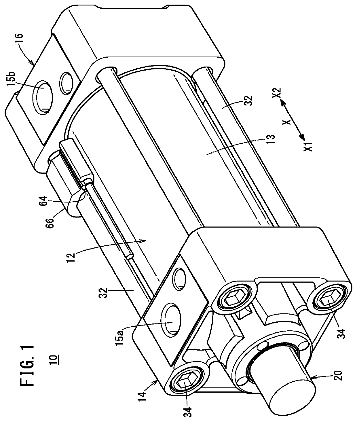
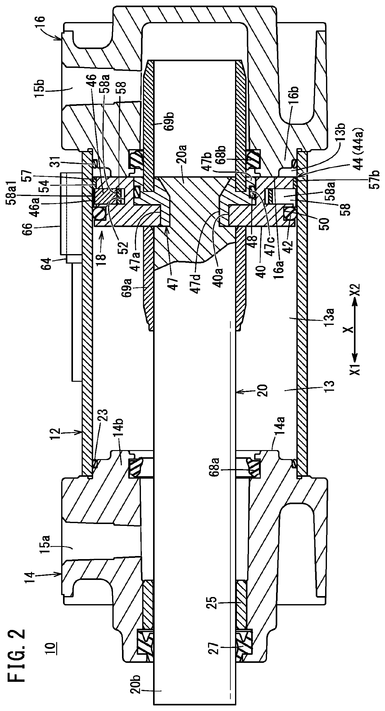
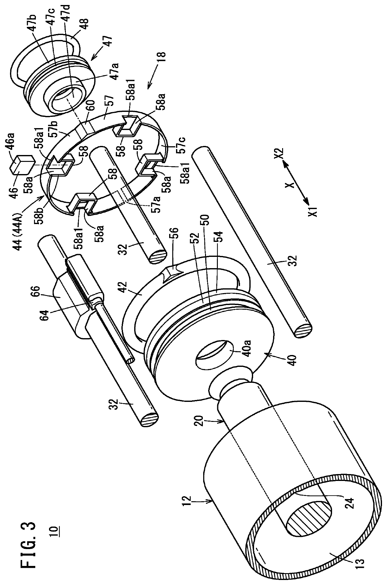
[0039]A fluid pressure cylinder 10 illustrated in FIG. 1 includes a hollow tubular cylinder tube 12 having a circular slide hole 13 (cylinder chamber) inside the cylinder tube 12, a rod cover 14 disposed at one end part of the cylinder tube 12, and a head cover 16 disposed at another end part of the cylinder tube 12. As illustrated in FIGS. 2 and 3, the fluid pressure cylinder 10 further includes a piston unit 18 disposed inside the cylinder tube 12 to be movable in the axial direction (X direction) and a piston rod 20 connected to the piston unit 18. The fluid pressure cylinder 10 is used as an actuator for, for example, carrying a workpiece.

[0040]The cylinder tube 12 is a tubular body composed of, for example, a metal material such as aluminum alloy and extends in the axial direction. In the first embodiment, the cylinder tube 12 has a hollow cylindrical shape.

[0041]A detent groove 24 extending in the axial direction of the cylinder tube 12 is provided in the inner circumferentia...

second embodiment

[0098]A fluid pressure cylinder 10a illustrated in FIG. 7 includes a hollow tubular cylinder tube 80 having the circular slide hole 13 inside the cylinder tube 80, a rod cover 82 disposed at one end part of the cylinder tube 80, a head cover 84 disposed at another end part of the cylinder tube 80, a piston unit 86 disposed inside the cylinder tube 80 to be movable in the axial direction (X direction), and a piston rod 88 connected to the piston unit 86.

[0099]The cylinder tube 80 has a hollow cylindrical shape. Internal thread portions 90a and 90b are formed on the inner circumferential surface of both end parts of the cylinder tube 80. The detent groove 24 (see FIG. 3) extending in the axial direction of the cylinder tube 80 is provided in the inner circumferential surface of the cylinder tube 80. Packings 92a and 92b with a circular ring shape are respectively disposed between the cylinder tube 80 and the rod cover 82 and between the cylinder tube 80 and the head cover 84.

[0100]Al...


PUM


Abstract

A hydraulic cylinder is provided with a cylinder tube, a piston unit, and a piston rod. The piston unit has a piston body; packing mounted on the piston body; a holding member mounted on the piston body; and a magnet held by a magnet holding part of the holding member. The magnet holding part has a notch that is open on the outer circumferential surface of the holding member.

Description

TECHNICAL FIELD[0001]The present invention relates to fluid pressure cylinders (hydraulic cylinders) including pistons on which magnets are disposed.BACKGROUND ART[0002]For example, fluid pressure cylinders including pistons displaced according to supply of pressurized fluid are well known as means for carrying workpieces and the like (actuators). A typical fluid pressure cylinder includes a cylinder tube, a piston disposed inside the cylinder tube to be movable in the axial direction, and a piston rod connected to the piston.[0003]In a fluid pressure cylinder disclosed in Japanese Laid-Open Patent Publication No. 2008-133920, a ring-shaped magnet is attached to an outer circumferential part of a piston, and a magnetic sensor is disposed outside a cylinder tube to detect the position of the piston. In this structure, the magnet has a ring shape (extends around the entire circumference) while the magnetic sensor is disposed on the cylinder tube only at a point in the circumferential ...

Claims


Application Information

Patent Timeline
Patent Type & Authority Applications(United States)
IPC IPC(8): F15B15/28F15B15/14
CPCF15B15/1423F15B15/2861F15B15/1447F15B15/1452F15B15/2807F15B15/2892F15B15/223F15B15/1414F15B15/14F15B15/1471
Inventor TAMURA, KEN
Owner SMC CORP
Why Eureka
Try Eureka