Load port apparatus and method of mounting container

Active Publication Date: 2020-09-24
TDK CORPARATION
View PDF0 Cites 0 Cited by
  • Summary
  • Abstract
  • Description
  • Claims
  • Application Information

AI Technical Summary

Benefits of technology

The present invention aims to provide a load port apparatus with a purge nozzle that can prevent particle generation during cleaning gas flow. A method is also provided to appropriately connect the purge nozzle with the purge port, while preventing excessive collision between them. This helps to prevent particulate matter from entering the flow channel for the cleaning gas. A further technical effect of this invention is the prevention of particle generation in the surrounding areas of the cleaning gas flow channel, which improves the efficiency and overall cleaning process.

Problems solved by technology

Such load port apparatuses need to vertically move the purge nozzle and may thereby have a problem of inflow of particles generated in a movable part of the purge nozzle into a flow channel of a cleaning gas to be introduced into the container.
When the purge nozzle excessively strongly collides with the purge port in the connection of the purge nozzle with the purge port, the conventional load port apparatuses have problems of short durability life due to progress of abrasion of the container, particle generation near the flow channel for the cleaning gas, and the like.

Method used


Image

  • Load port apparatus and method of mounting container
  • Load port apparatus and method of mounting container
  • Load port apparatus and method of mounting container

Examples


Embodiment Construction

[0056]Hereinafter, the present invention is explained based on an embodiment shown in the figures.

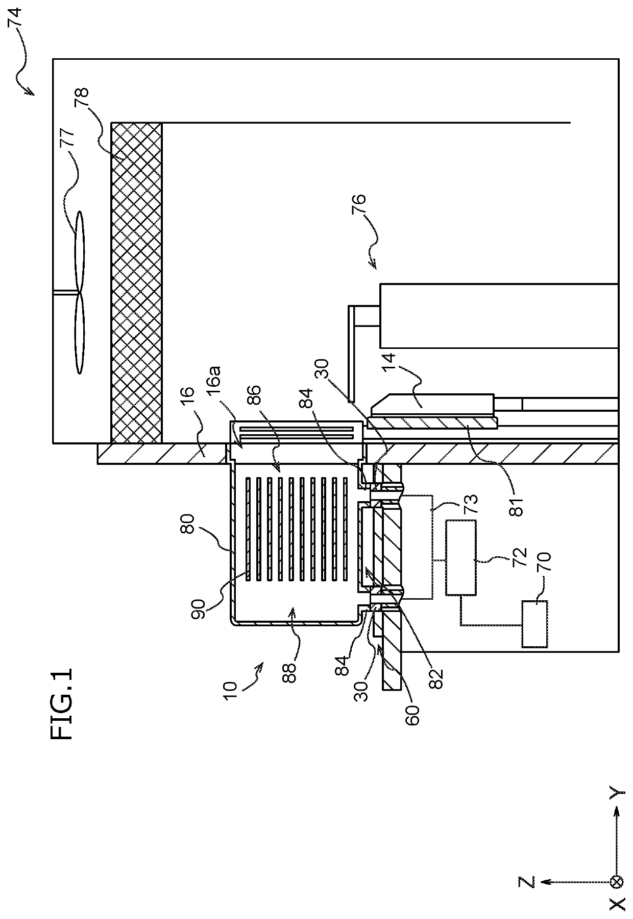
[0057]FIG. 1 is a schematic view of an EFEM 74 including a load port apparatus 10 according to an embodiment of the present invention and a container 80 mounted on the load port apparatus 10.

[0058]The load port apparatus 10 shown in FIG. 1 constitutes a part of the EFEM 74. The EFEM 74 forms a minienvironment provided with, for example, a transportation robot 76 for transporting substrates 90. The transportation robot 76 takes the substrates 90 (e.g., silicon wafer) contained in the container 80 connected to the minienvironment by the load port apparatus 10 and transports the substrates 90 into semiconductor processors.

[0059]The EFEM 74 includes a fan 77, a filter 78, and the like. The minienvironment formed in the EFEM 74 is maintained in a clean environment.

[0060]The container 80 is a container used for transporting the substrates 90 to be processed to each processor in a semiconducto...


PUM


Abstract

A load port apparatus includes a mount member, a purge nozzle, and a plurality of pins. The mount member mounts a container. The nozzle introduces a cleaning gas into the container mounted on the mount member via a purge port disposed on a bottom of the container. The pins support the container from below by each contacting with a predetermined position of the bottom of the container. The pins are relatively vertically movable to the mount member between a first position and a second position where an upper tip of each of the pins is located lower than that at the first position. The upper tip of each of the pins at the first position contacts with the predetermined position of the container. The upper tip of each of the pins at the second position contacts with the predetermined position of the container.

Description

BACKGROUND OF THE INVENTION[0001]The present invention relates to a load port apparatus for mounting a container for containing a substrate and to a method of mounting the container.[0002]In semiconductor factories, substrates (e.g., silicon wafers) are transported and stored using a container containing the substrates. The container is sealed, but the cleanliness of the container may decrease due to outgas generated from the contained substrates, leak and gas permeation from a sealed part of the container.[0003]Then, thereby proposed as load port apparatuses for delivering a container in semiconductor factories is one including a purge nozzle for gas purge from the bottom of the container. The load port apparatus including the purge nozzle connects the purge nozzle with a purge port disposed on the bottom of the container and can introduce a cleaning gas into the container via the purge nozzle.[0004]Patent Document 1: JP2011187539 (A)BRIEF SUMMARY OF INVENTION[0005]In conventional ...

Claims


Application Information

Patent Timeline
IPC IPC(8): H01L21/673H01L21/677H01L21/687
CPCH01L21/67393H01L21/68742H01L21/6773H01L21/67775
Inventor IWAMOTO, TADAMASA
Owner TDK CORPARATION
Why Eureka
Try Eureka