System and method for child-birth monitoring and assistance

Inactive Publication Date: 2020-10-01
GHODSIAN KAMRAN
View PDF0 Cites 2 Cited by
  • Summary
  • Abstract
  • Description
  • Claims
  • Application Information

AI Technical Summary

Benefits of technology

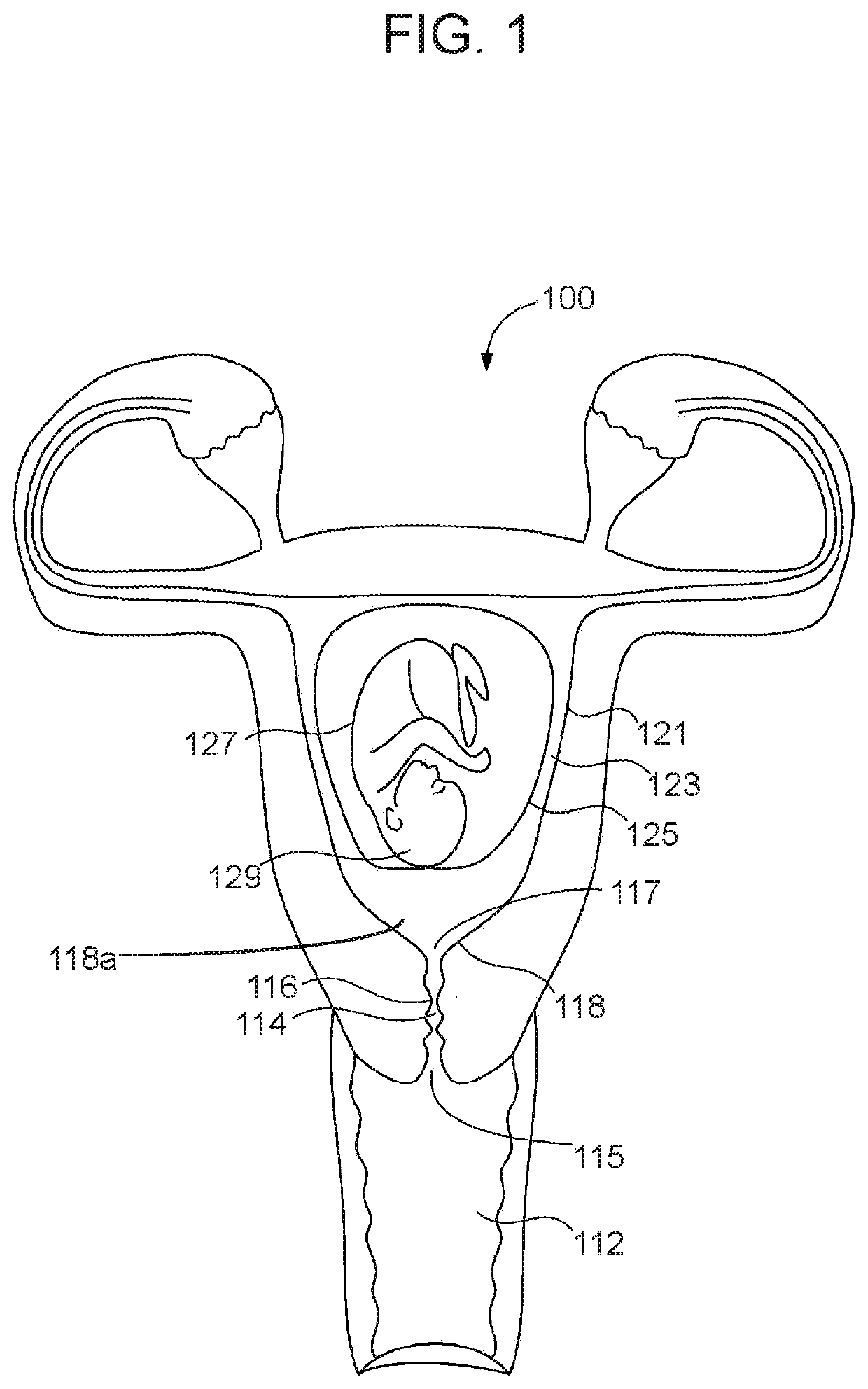
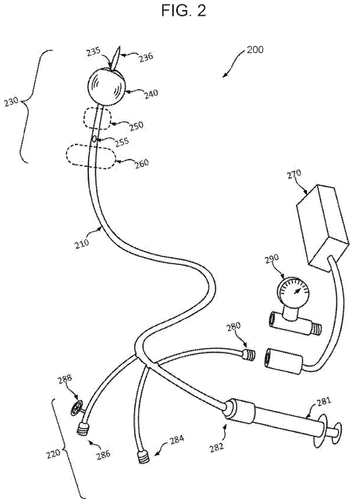
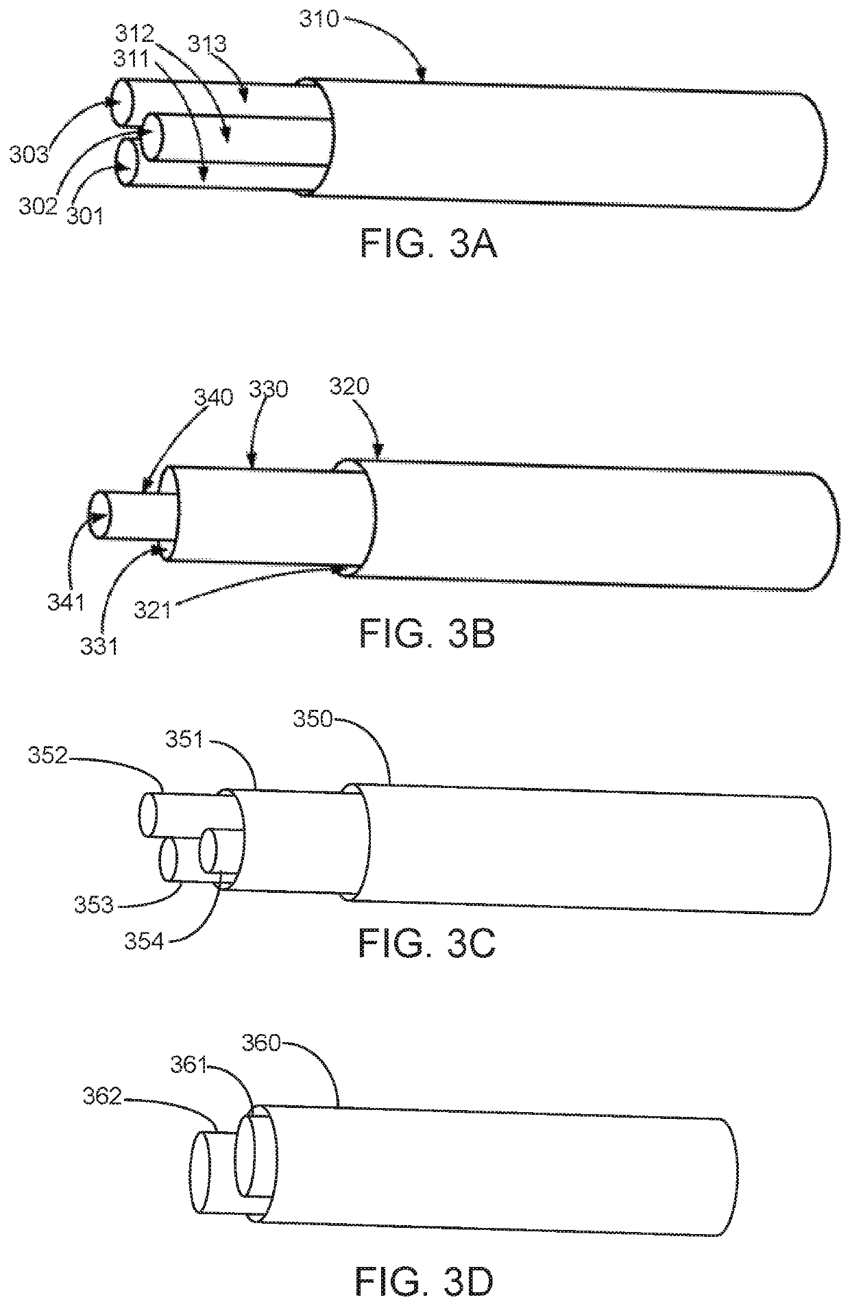
The invention is about creating a system to monitor and measure the pressure inside a woman's uterus without breaking the amniotic sac. The system involves a pressure sensing module and a single or multi-balloon catheter. The catheter is inserted through the cervix and positioned in the lower segment of the uterus, resting against the amniotic sac. The balloon is connected to the pressure sensing module, so any pulsations of the amniotic sac will be sensed and measured. This way, changes in intrauterine pressure during labor can be observed without rupturing the amniotic sac.

Problems solved by technology

However, it is extremely difficult, if not impossible, to administer 3 ml of gel in a strictly endocervical fashion without applying some of the gel retroamniotically, which may cause side effects to uterine hypercontractility, and may lead to fetal distress.
Intracorporeal labor induction systems of the prior art do not control or measure uterus / amniotic-fluid pressure.
By clogging the cervical canal, the existing systems make it hard, if not impossible, to insert a separate pressure measuring instrument into a patient's reproductive system to measure uterus and amniotic-fluid pressures.
Furthermore, available uterus / amniotic-fluid pressure measurement devices are inherently inaccurate.
However, known methods often rely on apparatus or devices that are inherently inaccurate and often cause or require the amniotic sac to be ruptured.
Current methods inadequately address this need.
Accordingly, the prior art inadequately addresses labor monitoring systems that: (i) may induce labor while accurately measuring the uterus and amniotic fluid pressure without rupturing the amniotic sac, (ii) facilitate control of the uterus and amniotic fluid pressure without rupturing the amniotic sac, and (iii) facilitate measuring and or observing a frequency of uterine contractions, without rupturing the amniotic sac.

Method used


Image

  • System and method for child-birth monitoring and assistance
  • System and method for child-birth monitoring and assistance
  • System and method for child-birth monitoring and assistance

Examples


Embodiment Construction

[0034]In the following discussion that addresses a number of embodiments and applications of the present invention, reference is made to the accompanying drawings, which form a part thereof. Depictions are made, by way of illustration, of specific embodiments in which the invention may be practiced; however, it is to be understood that other embodiments may be utilized, and changes may be made without departing from the scope of the present invention. Wherever possible, the same reference numbers are used in the drawings and the following description to refer to the same or similar elements.

[0035]In the following detailed description, numerous specific details are set forth by way of examples in order to provide a thorough understanding of the relevant teachings. However, it should be apparent to those skilled in the art that the present teachings may be practiced without such details. In other instances, well-known structures, components, and / or functional or structural relationshi...


PUM


Abstract

The invention is generally a system, apparatus, and method for monitoring and measuring a change in intrauterine pressure without rupturing the amniotic sac. A catheter is coupled to a pressure sensing module. The pressure sensing module is configured with a chamber that is in fluid communication with a balloon of the catheter. The chamber includes a pressure-sensing membrane coupled to sensing circuitry. The sensing circuitry is configured to detect a pressure applied to the pressure-sensing membrane and communicate the condition to a monitor of the system. Methods include inserting the catheter through the cervix so that the balloon may be inflated and situated in the lower segment of the uterus, resting against the amniotic sac. Because the balloon of the catheter is in fluid communication with the pressure-sensing membrane, pulsations of the amniotic sac will be sensed by the sensing circuitry of the pressure sensing module.

Description

TECHNICAL FIELD OF THE INVENTION[0001]The present invention relates generally to processes of child-birth monitoring and assistance. More specifically, the present invention relates to a system, apparatus, and method for monitoring and measuring a change in intrauterine pressure during labor, without rupturing the amniotic sac.COPYRIGHT AND TRADEMARK NOTICE[0002]A portion of the disclosure of this patent application may contain material that is subject to copyright protection. The owner has no objection to the facsimile reproduction by anyone of the patent document or the patent disclosure, as it appears in the Patent and Trademark Office patent file or records, but otherwise reserves all copyrights whatsoever.[0003]Certain marks referenced herein may be common law or registered trademarks of third parties affiliated or unaffiliated with the applicant or the assignee. Use of these marks is by way of example and should not be construed as descriptive or to limit the scope of this inv...

Claims


Application Information

Patent Timeline
IPC IPC(8): A61B5/03A61B5/00A61B1/303
CPCA61B1/303A61B2562/0271A61B2562/0247A61B5/6875A61B5/035A61B5/6853A61B5/02055A61B5/6885A61B2503/02A61B5/02411A61B5/344
Inventor GHODSIAN, KAMRAN
Owner GHODSIAN KAMRAN
Why Eureka
Try Eureka