Device for use in fluid sample analysis

a technology for fluid sample analysis and devices, applied in measurement devices, laboratory glassware, instruments, etc., can solve problems such as insufficient reflection ligh

Active Publication Date: 2020-10-01
SIEMENS HEALTHINEERS NEDERLAND BV
View PDF0 Cites 0 Cited by
  • Summary
  • Abstract
  • Description
  • Claims
  • Application Information

AI Technical Summary

Benefits of technology

[0005]It would be advantageous to have an i

Problems solved by technology

If the membrane is not present, not only is sample fluid not transferred to the measurement zone there is ins

Method used


Image

  • Device for use in fluid sample analysis
  • Device for use in fluid sample analysis
  • Device for use in fluid sample analysis

Examples


Embodiment Construction

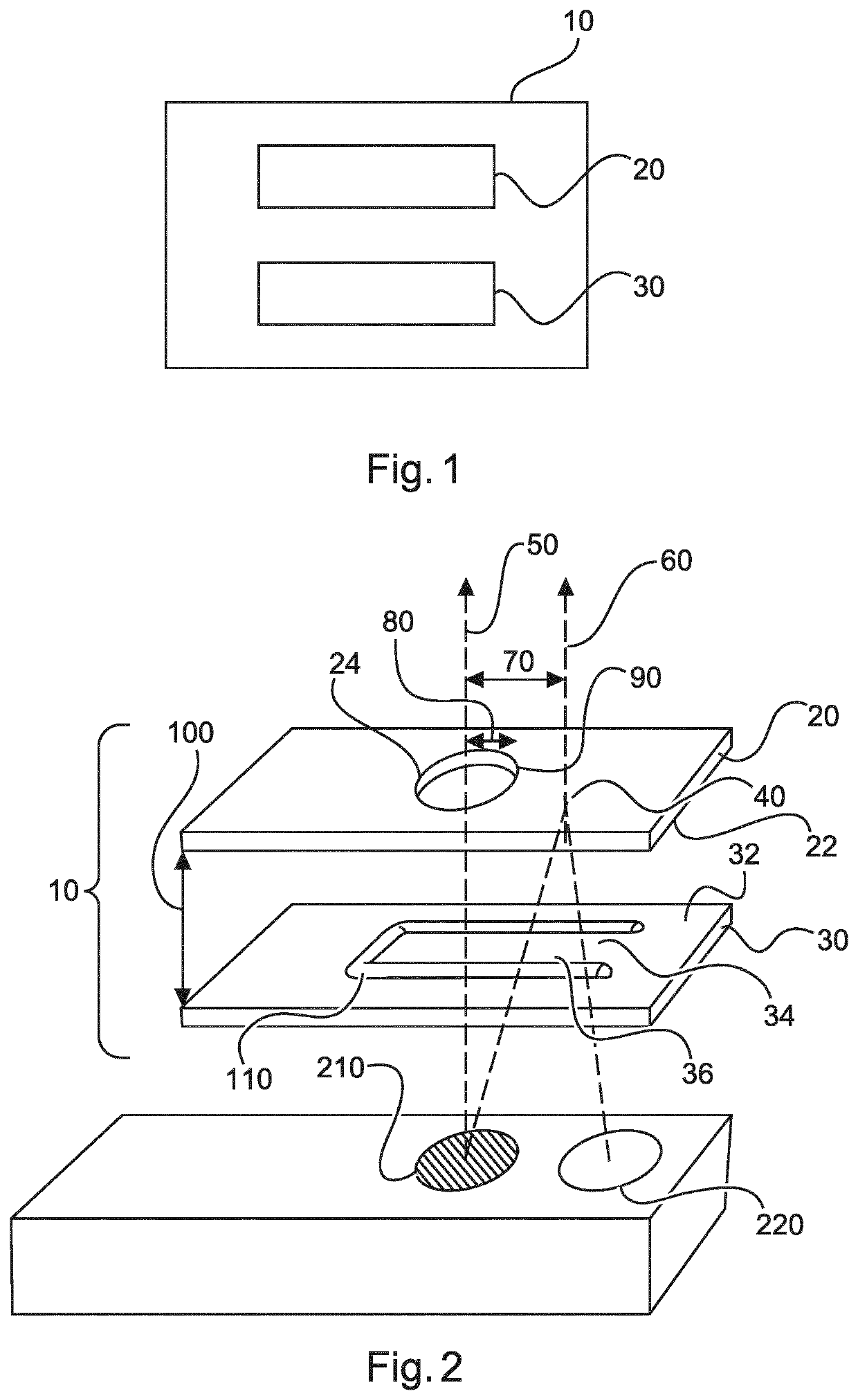
[0059]FIGS. 1 and 2 show a device 10 for use in fluid sample analysis. The device 10 comprises a top part 20, and a base part 30. The top part 20 is configured to be positioned adjacent to the base part 30 so as to define a fluid receiving region 100 in between. The top part 20 has a through opening 24 so as to enable fluid connection with the fluidic receiving region. A fluid sample is not shown in FIG. 1, but can be seen in FIG. 6. The base part 30 comprises a fluid receiving surface 34, and a radiation window 36 extending from at least a part of the fluid receiving surface 34. When the top part 20 is positioned adjacent to the base part 30, the device 10 is configured such that a fluidic sample supplied through the opening 24 is moved laterally in the fluid receiving region over the fluid receiving surface 34 without the use of an intermediary membrane. The device further comprises a radiation receiving area 40 that is at least partially reflective to at least one wavelength of t...


PUM


Abstract

The present invention relates to a device (10) for use in fluid sample analysis. It is described to position (310) a top part (20) of the device (10) adjacent to a base part (30) of the device so as to define a fluidic receiving region in between, the top part being provided with a through opening fluidly connected to the fluidic receiving region, and the bottom part being provided with a radiation window adjacent to the fluidic receiving region. A fluidic sample is supplied (320) through the opening (24). The fluidic sample is moved laterally (330) in the fluid receiving region without the use of an intermediary membrane between the top part and the base part. A radiation is emitted (340) to the fluid receiving region. A radiation is detected (350) that is reflected by the device. A presence of the fluidic sample is determined (360) on the basis of a measured reflectance value based on the detected radiation.

Description

FIELD OF THE INVENTION[0001]The present invention relates to a device for use in fluid sample analysis, system for fluid sample analysis, and to a method for use in fluid sample analysis, as well as to a computer program element and a computer readable medium.BACKGROUND OF THE INVENTION[0002]Fluid sample analysis is performed using a disposable cartridge within which the fluid sample is supplied, and an analyser within which the cartridge is inserted for diagnostic testing. For a test, the cartridge is inserted into the analyser and a sample fluid is added to the sample interface of the cartridge. The sample fills a cartridge, after which the analyser starts the measurement. A filtering membrane is provided within the cartridge, which has a filtering function and also transfers the sample to a measurement zone via wicking. Before starting the sample analysis, a preliminary check is made to determine whether a fluid sample is actually in the cartridge. Wetting of the membrane by bloo...

Claims


Application Information

Patent Timeline
IPC IPC(8): G01N21/03B01L3/00
CPCB01L3/50273B01L2400/049B01L2400/0406B01L2300/0809B01L3/502715B01L2300/0851B01L2300/06G01N21/0303G01N2021/0346B01L2300/168G01N21/01B01L3/545B01L2200/025B01L2200/04B01L2200/0684B01L2300/022B01L2300/023B01L2300/024B01L2300/027B01L2300/0654B01L2300/0887B01L2300/161
Inventor VAN REENEN, ALEXANDERVAN ROOSMALEN, MARKUS HENDRIKUSVAN DAMME, HENDRIK SIBOLT
Owner SIEMENS HEALTHINEERS NEDERLAND BV
Why Eureka
Try Eureka