
SYSTEM AND METHOD FOR IMPLEMENTING FUNCTIONAL LOGICS OF VERIFICATION IP USING STATE DESIGN PATTERN BASED FSMs

a functional logic and state design technology, applied in the field of verification systems, can solve the problems of increasing the complexity of the functional logic implemented, increasing the redundancy of the code, and increasing the performance, so as to improve the modularity and observability of the verification ip, and reduce code redundancy. , the effect of improving the controllability

Active Publication Date: 2020-10-01
SILICONCH SYST PVT LTD
View PDF0 Cites 0 Cited by
  • Summary
  • Abstract
  • Description
  • Claims
  • Application Information

AI Technical Summary

Benefits of technology

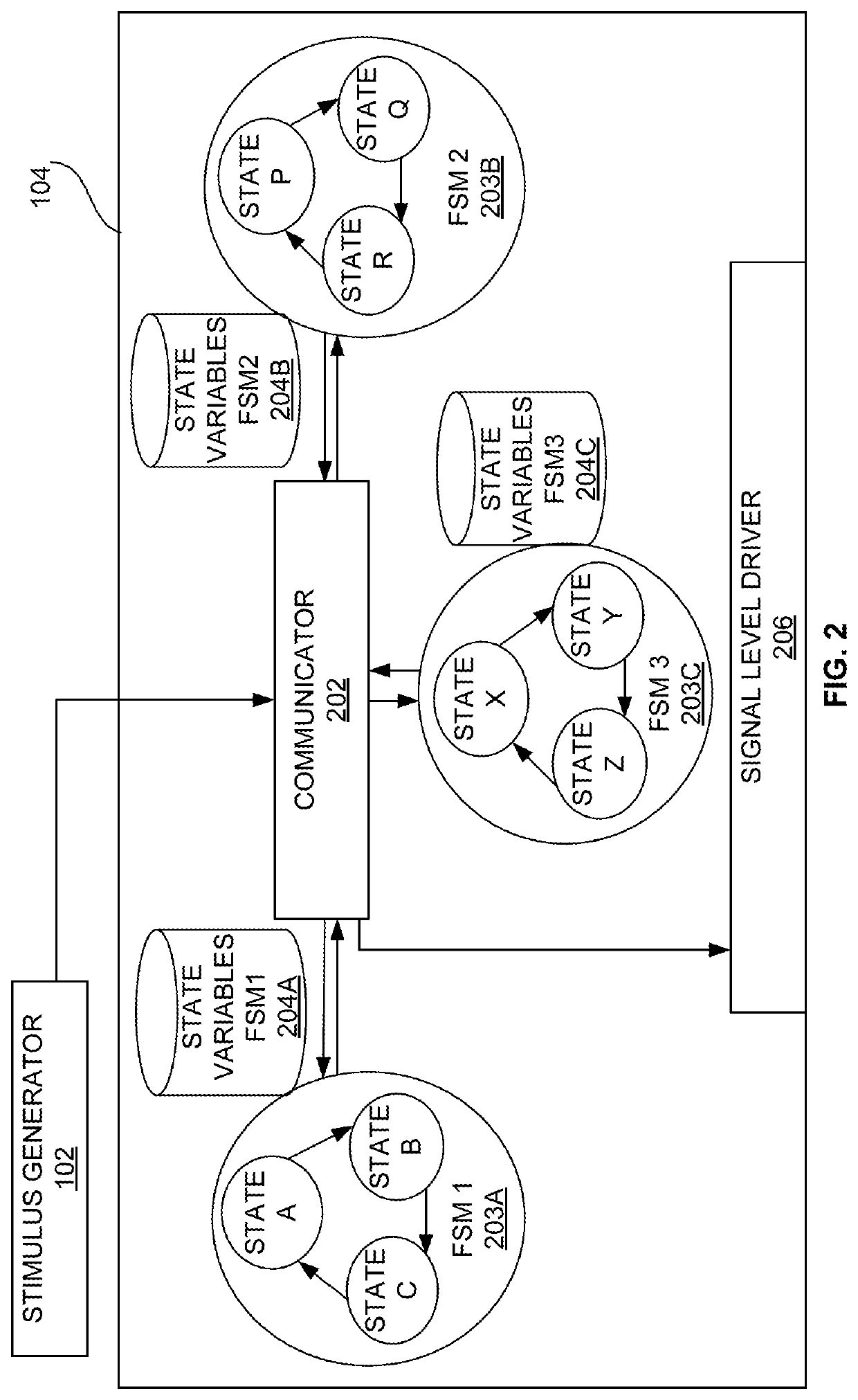
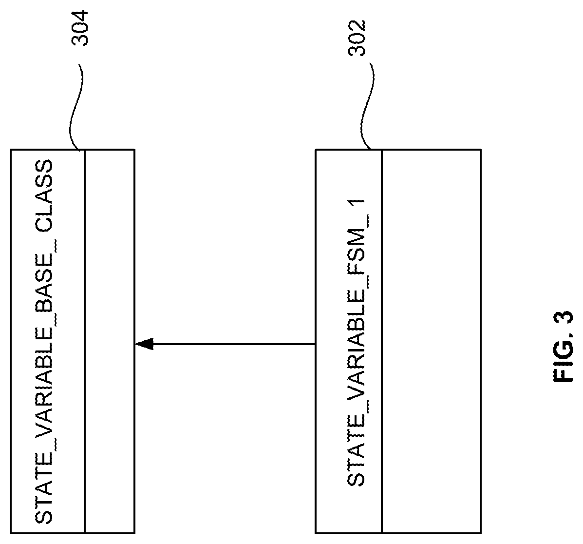
The present invention provides a way to control the operations of a verification IP used for testing a DUT. The architecture uses state classes and finite state machines to modify the functional operation of the verification IP without needing to modify the original code. This improves controllability, modularity, and observability of the verification IP. Additionally, the architecture reduces code redundancy by dividing the code into multiple states over multiple FSMs, meaning only the modified implementation for a state is needed when error injection is required.

Problems solved by technology

This implies increased redundancy of the code with an increase in complexity of the functional logic implemented in Verification IP.
Moreover, for scenarios where modification of a large functional logic is needed, multiple callbacks might be required which increasingly hit the performance.
Though, similar architectures have been proposed for implementation of the functional logic of Verification IPs, none of architecture avoids redundancy and without compromising the performance of the Verification IPs.

Method used


Image

  • SYSTEM AND METHOD FOR IMPLEMENTING FUNCTIONAL LOGICS OF VERIFICATION IP USING STATE DESIGN PATTERN BASED FSMs
  • SYSTEM AND METHOD FOR IMPLEMENTING FUNCTIONAL LOGICS OF VERIFICATION IP USING STATE DESIGN PATTERN BASED FSMs
  • SYSTEM AND METHOD FOR IMPLEMENTING FUNCTIONAL LOGICS OF VERIFICATION IP USING STATE DESIGN PATTERN BASED FSMs

Examples


Embodiment Construction

[0036]The embodiments herein and the various features and advantageous details thereof are explained more fully with reference to the non-limiting embodiments that are illustrated in the accompanying drawings and detailed in the following description. Descriptions of well-known components and processing techniques are omitted so as to not unnecessarily obscure the embodiments herein. The examples used herein are intended merely to facilitate an understanding of ways in which the embodiments herein may be practiced and to further enable those of skill in the art to practice the embodiments herein. Accordingly, the examples should not be construed as limiting the scope of the embodiments herein.

[0037]As mentioned, there remains a need of a system and a method for architecting the functional logics of Verification IP (VIP) to enable more controllability, observability and modularity of the Verification IP unit. The embodiments herein achieve this by providing an architecture of functio...


PUM


Abstract

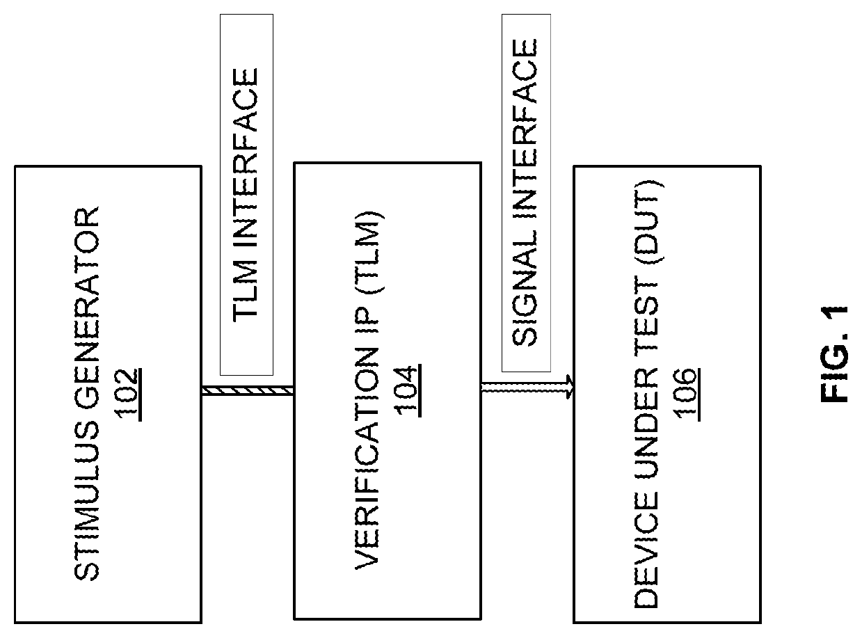
A system for implementing functional logics of a verification IP using a transaction level modeling (TLM) is provided. The system includes (A) a stimulus generator to initiate a transaction and transmit the transaction through a transaction level model interface, (B) a verification IP unit to receive and process the transaction and (C) a signal-level driver to toggle pins of the design under test (DUT) based on the processed transaction. The verification IP unit is configured to (a) divide functional logics of a verification IP unit into one or more finite state machines (FSMs) when a transaction is received from a stimulus generator, (b) define a set of state variables for each of the one or more FSMs, (c) implement a state class for each state of the one or more FSMs and (d) modify the functionality of the one or more FSMs.

Description

BACKGROUNDTechnical Field[0001]The embodiments herein generally relate to a verification system, and, more particularly, to a system and method for implementing functional logics of verification IP using a transaction level modeling.Description of the Related Art[0002]A Verification Intellectual Property (VIP), in general, represents a unit, modeled behaviorally, to drive input signals into a Design Under Test (DUT) and verify the correctness of the output signals from DUT. VIPs used in functional verification of a DUT are mostly developed as Transaction Level Models (TLMs) in UVM / OVM. Hence, a VIP, for functionally verifying a protocol, contains processing of transaction(s) generated by a Testcase / Stimulus Generator, and eventually converting the encapsulating transaction(s) into DUT pin toggling. The functional logics of a Verification IP may scale from a simple Bus Functional Model (BFM) for signaling the DUT to a multi-layered protocol model for processing the transaction at eac...

Claims


Application Information

Patent Timeline
IPC IPC(8): G06F17/50G06Q50/18
CPCG06F30/3323G06Q50/184G06F2115/08G06F30/3308
Inventor KUMAR, KAUSTUBHBALASUBRAMANIAN, PAVITRA
Owner SILICONCH SYST PVT LTD
Learn More