Multilayer ceramic capacitor and method for manufacturing multilayer ceramic capacitor

a multi-layer ceramic and capacitor technology, applied in the direction of fixed capacitors, stacked capacitors, fixed capacitor details, etc., can solve the problems of not having strong adhesion (or large bonding strength), external electrode damage, peeling, etc., and achieve large moisture resistance and strength.

Active Publication Date: 2020-10-01
MURATA MFG CO LTD
View PDF0 Cites 4 Cited by
  • Summary
  • Abstract
  • Description
  • Claims
  • Application Information

AI Technical Summary

Benefits of technology

The invention provides multilayer ceramic capacitors with strong external electrodes that have good moisture resistance. The method for manufacturing these capacitors is also provided.

Problems solved by technology

However, the underlying electrode layer mainly composed of Ni and the Cu plating electrode layer are different in material and how they are formed, and thus do not have strong adhesion (or large bonding strength).
Therefore, in the multilayer ceramic capacitor disclosed in Japanese Patent Laid-Open No. 2017-168488, peeling may occur between the underlying electrode layer mainly composed of Ni and the Cu plating electrode layer, and the external electrodes may be damaged.
In addition, moisture reaches the internal electrodes through a gap formed by peeling between the underlying electrode layer mainly composed of Ni and the Cu plating electrode layer or the like, and the multilayer ceramic capacitor may have characteristics that are impaired due to poor moisture resistance.
However, Japanese Patent Laid-Open No. 2012-9813 does not disclose to what extent the metal in the underlying electrode layer should be diffused into the Cu plating electrode layer.
Therefore, if the heat treatment for diffusing the metal contained in the underlying electrode layer into the Cu plating electrode layer is excessively performed, the first multilayer ceramic capacitor disclosed in Japanese Patent Laid-Open No. 2012-9813 would have the Cu plating electrode layer with its front and back sides connected through the voids, and there is a possibility that the external electrodes (the Cu plating electrode layer) may have reduced moisture resistance.
Further, even if the heat treatment for diffusing the metal contained in the underlying electrode layer into the first Cu plating electrode layer is excessively performed, the second multilayer ceramic capacitor disclosed in Japanese Patent Laid-Open No. 2012-9813 maintains sufficient moisture resistance as the second Cu plating electrode layer exists.
However, manufacturing the second multilayer ceramic capacitor disclosed in Japanese Patent Laid-Open No. 2012-9813 requires the step of forming the first Cu plating electrode layer and the step of forming the second Cu plating electrode layer, which is cumbersome and less productive.

Method used


Image

  • Multilayer ceramic capacitor and method for manufacturing multilayer ceramic capacitor
  • Multilayer ceramic capacitor and method for manufacturing multilayer ceramic capacitor
  • Multilayer ceramic capacitor and method for manufacturing multilayer ceramic capacitor

Examples


first preferred embodiment

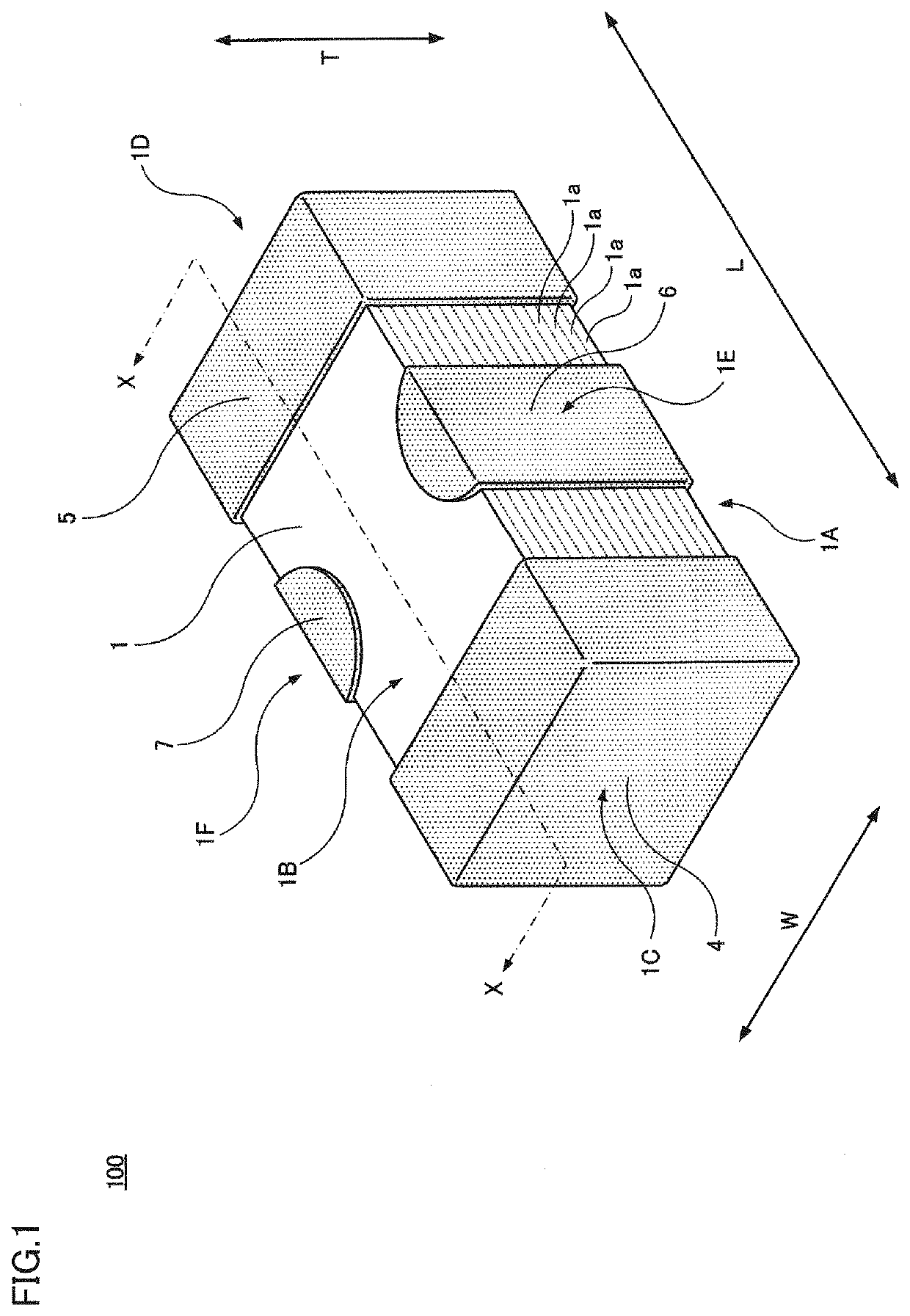
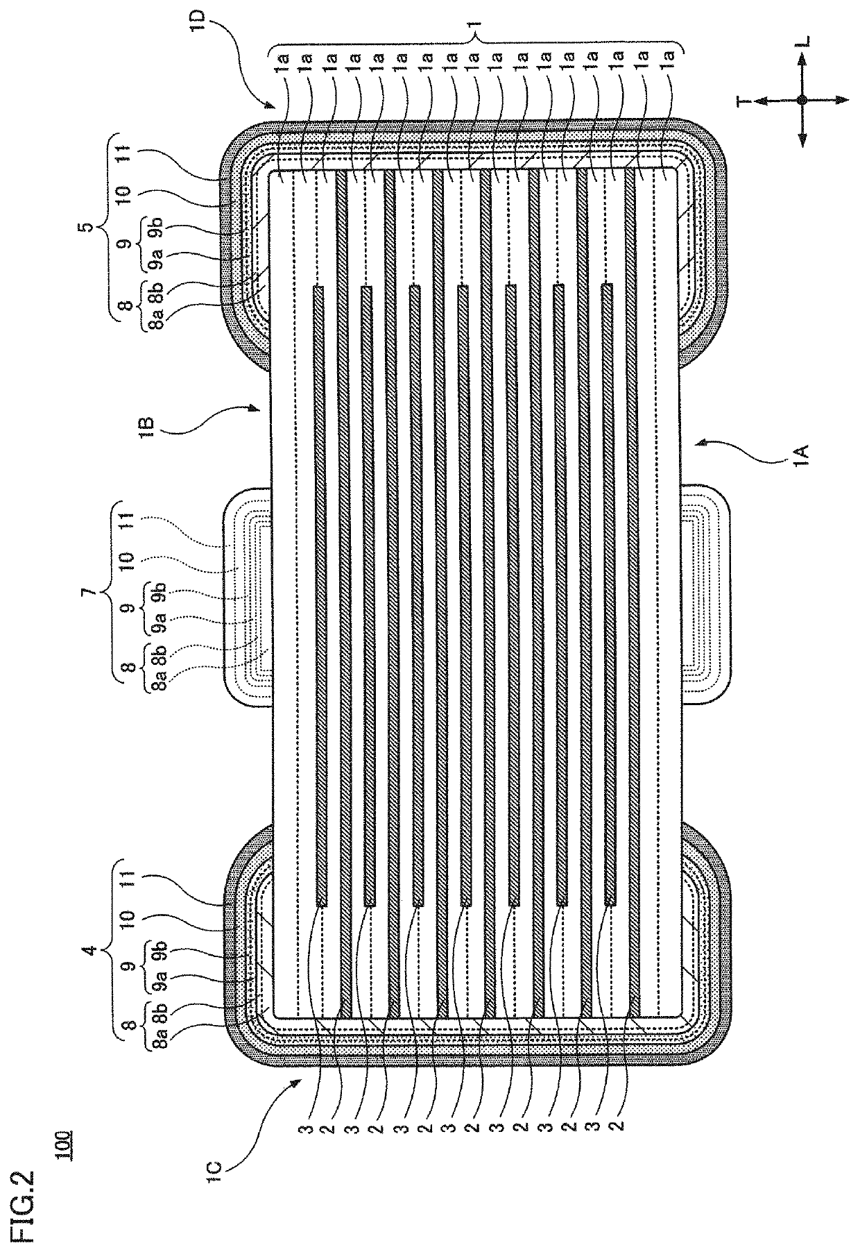
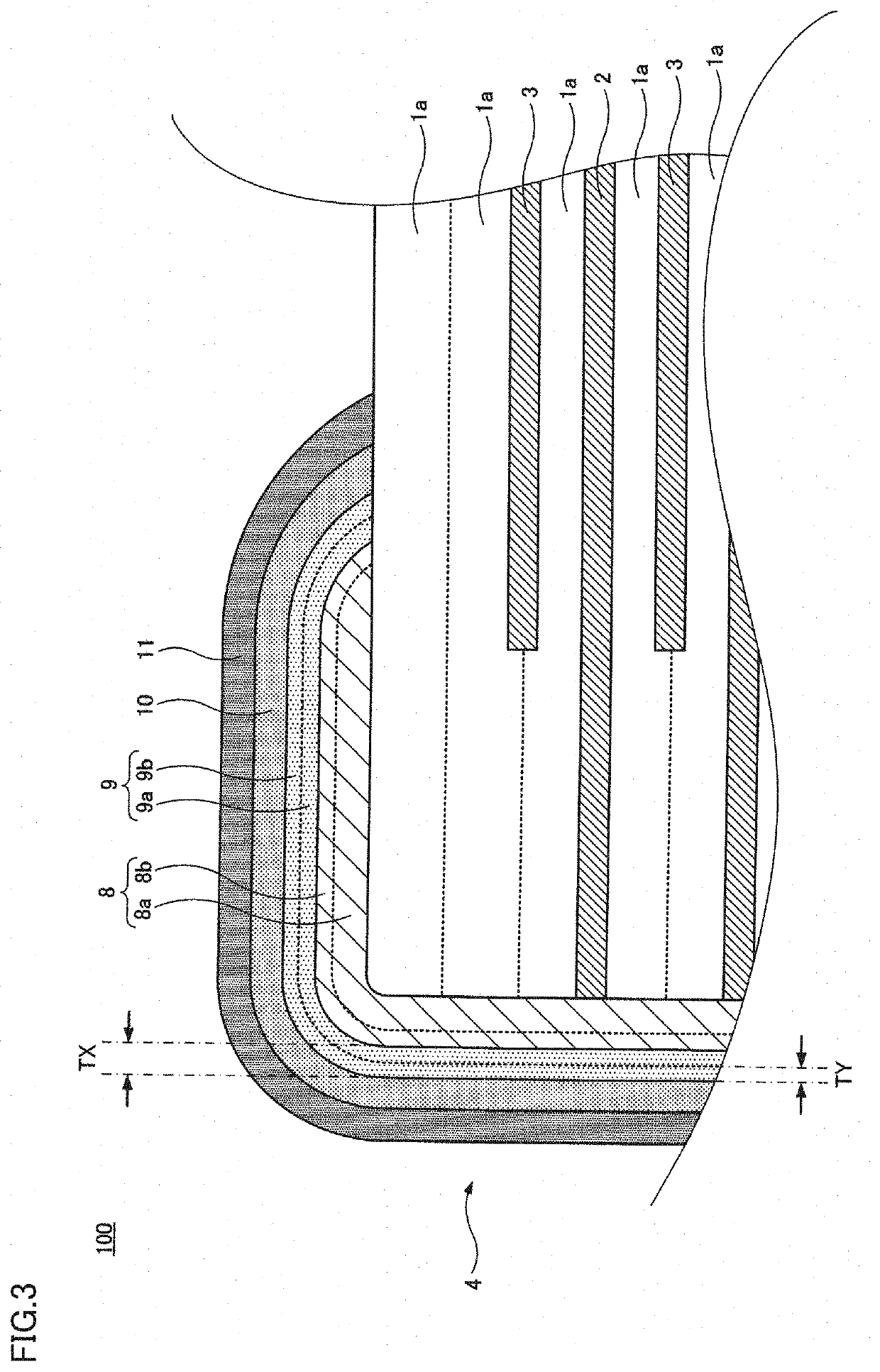
[0029]FIGS. 1 to 4 show a multilayer ceramic capacitor 100 according to a first preferred embodiment of the present invention. FIG. 1 is a perspective view of multilayer ceramic capacitor 100. FIG. 2 is a cross section of multilayer ceramic capacitor 100, and shows a portion X-X indicated in FIG. 1 by an arrowed, one-dot chain line. FIG. 3 is a cross section of a main portion of multilayer ceramic capacitor 100. FIG. 4 is an exploded perspective view of multilayer ceramic capacitor 100. The figures indicate a heightwise direction T, a lengthwise direction L, and a widthwise direction W of multilayer ceramic capacitor 100, and these directions may be referred to in the following description. In the present preferred embodiment, a direction in which ceramic layers 1a described hereinafter are stacked is defined as heightwise direction T of multilayer ceramic capacitor 100.

[0030]Multilayer ceramic capacitor 100 includes capacitive element 1 having a rectangular or substantially rectang...

second preferred embodiment

[0105]FIGS. 5 and 6 show a multilayer ceramic capacitor 200 according to a second preferred embodiment of the present invention. FIG. 5 is a perspective view of multilayer ceramic capacitor 200. FIG. 6 is a cross section of multilayer ceramic capacitor 200, and shows a portion Y-Y indicated in FIG. 5 by an arrowed, one-dot chain line.

[0106]Multilayer ceramic capacitor 200 according to the second preferred embodiment corresponds to multilayer ceramic capacitor 100 according to the first preferred embodiment having a partially modified configuration. Specifically, while multilayer ceramic capacitor 100 is a three-terminal capacitor, multilayer ceramic capacitor 200 is preferably a two-terminal capacitor, for example.

[0107]Multilayer ceramic capacitor 200 includes capacitive element 1 including a plurality of ceramic layers 1a and a plurality of internal electrodes 22 and 23 disposed in layers. Internal electrodes 22 and 23 both extend in lengthwise direction L and have a rectangular o...


PUM

PropertyMeasurementUnit
Lengthaaaaaaaaaa
Timeaaaaaaaaaa
Thicknessaaaaaaaaaa

Abstract

A multilayer ceramic capacitor includes a capacitive element including ceramic layers and internal electrodes, and external electrodes on the capacitive element. The external electrodes include a Ni underlying electrode layer mainly made of Ni, a Cu plating electrode layer, and at least one second plating electrode layer. The Cu plating electrode layer includes a Ni diffused Cu plating electrode layer on a side closer to the Ni underlying electrode layer and including Ni diffused therein and a non-Ni diffused Cu plating electrode layer on a side closer to the second plating electrode layer and not including Ni diffused therein. The Cu plating electrode layer has a thickness of about 3 μm or more and about 12 μm or less and the non-Ni diffused Cu plating electrode layer has a thickness of about 0.5 μm or more.

Description

CROSS REFERENCE TO RELATED APPLICATIONS[0001]This application claims the benefit of priority to Japanese Patent Application No. 2019-064996 filed on Mar. 28, 2019. The entire contents of this application are hereby incorporated herein by reference.BACKGROUND OF THE INVENTION1. Field of the Invention[0002]The present invention relates to a multilayer ceramic capacitor, and more particularly, to a multilayer ceramic capacitor having improved moisture resistance and an external electrode having improved strength, and to a method for manufacturing a multilayer ceramic capacitor.2. Description of the Related Art[0003]A typical multilayer ceramic capacitor includes a capacitive element in which a plurality of ceramic layers and a plurality of internal electrodes are deposited in layers, and has external electrodes formed on an external surface of the capacitive element. The internal electrodes are drawn out to the end, side or other surfaces of the capacitive element and connected to the ...

Claims


Application Information

Patent Timeline
IPC IPC(8): H01G4/30H01G4/232H01G4/12H01G4/012
CPCH01G4/30H01G4/2325H01G4/1209H01G4/012H01G4/232
Inventor KANZAKI, TAISUKEMURAMATSU, SATOSHIONISHI, KOSUKE
Owner MURATA MFG CO LTD
Why Eureka
Try Eureka