Spring forming machine having tool rotation and tool retraction capabilities

a spring forming machine and tool technology, applied in the field of spring forming machines, can solve the problems of inability to retraction, low yield and production efficiency, and technical difficulties, and achieve the effects of reducing time, eliminating jamming and failure of tool retraction, and smooth tool rotation and tool retraction

Active Publication Date: 2020-10-08
HUIZHOU ODMAY MACHINERY CO LTD
View PDF0 Cites 2 Cited by
  • Summary
  • Abstract
  • Description
  • Claims
  • Application Information

AI Technical Summary

Benefits of technology

[0007]The objective of the present invention is to provide a spring forming machine having tool rotation and tool retraction capabilities, that is capable of realizing smooth tool rotation and tool retraction, reducing the time caused by multi-processing or reworks of the spring, and eliminating jamming and failure of tool retraction. In this way, the present invention is able to solve the technical difficulties of the Prior Art, such as tool not being able to be retracted, jamming of the tools, or not being able to pull back the tool.
[0008]In order to achieve the objective mentioned above, the technical characteristics of the present invention is that, through the inner circle core rotation transmission mechanism and the outer circle tool rotation transmission mechanism disposed in the rear part of the rotary beak seat mechanism, the two round discs on the

Problems solved by technology

1. When the tool rotates 360 degrees around the axle core, the tool must rotate synchronously together with the axle core (unitary transmission). The tool is not able to rotate independently, thus it can only bend, twist the wire along the direction of the axle core. As such, it lacks flexibility, and is liable to being jammed. Therefore, in the spring forming process, the processing blind angle may occur quite often, and that leads to processing difficulties. In this process, se

Method used


Image

  • Spring forming machine having tool rotation and tool retraction capabilities
  • Spring forming machine having tool rotation and tool retraction capabilities
  • Spring forming machine having tool rotation and tool retraction capabilities

Examples


Embodiment Construction

[0025]The purpose, construction, features, functions and advantages of the present invention and its embodiments can be appreciated and understood more thoroughly through the following detailed descriptions with reference to the attached drawings.

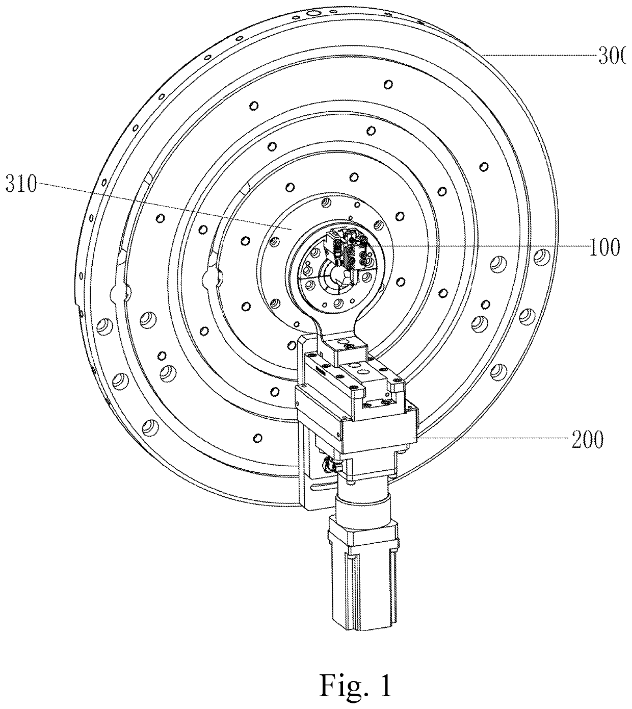
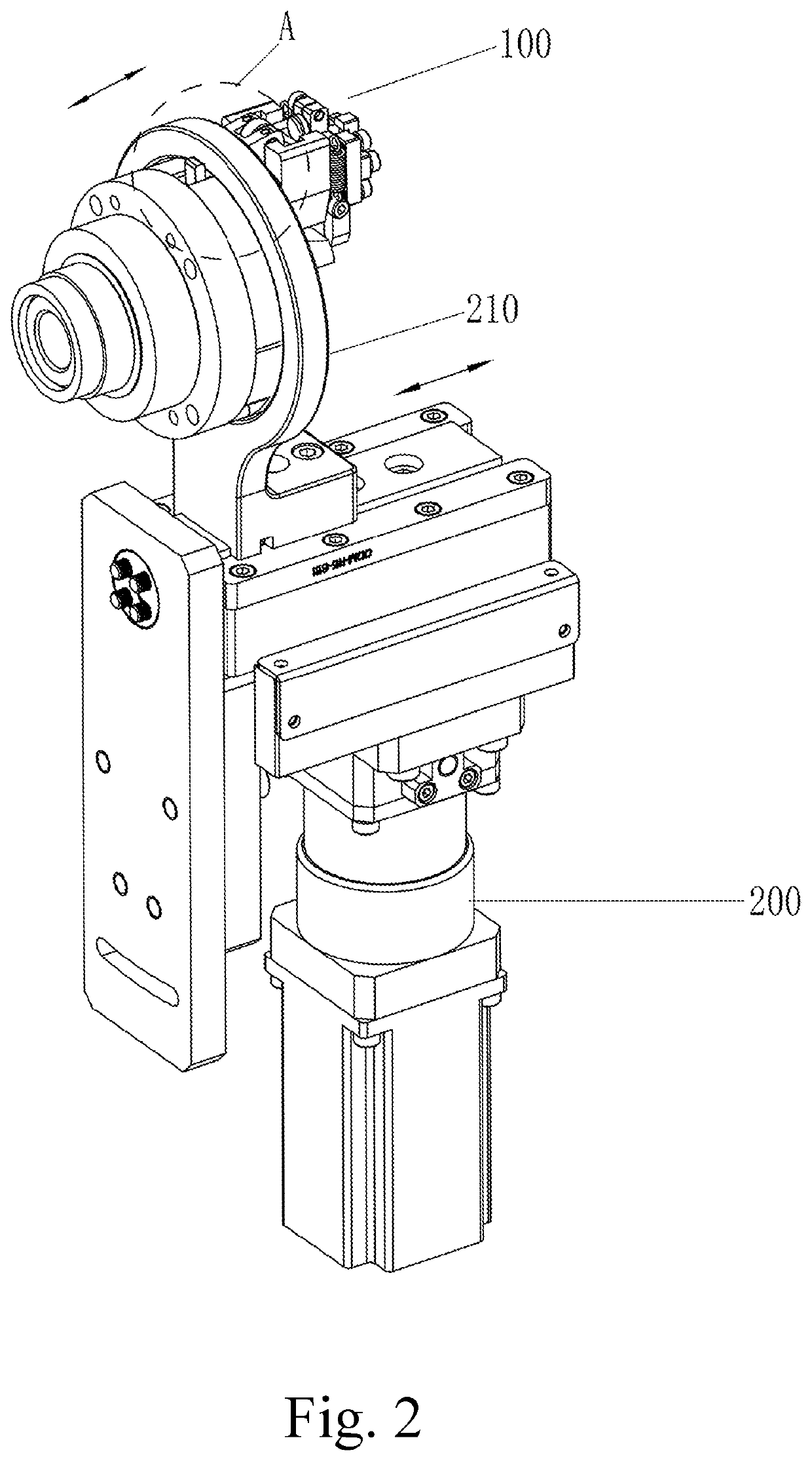
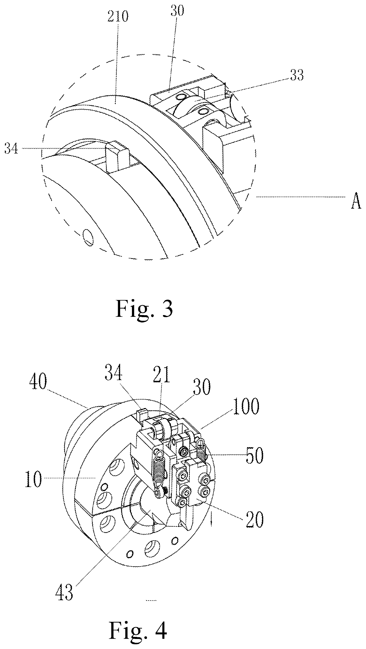
[0026]Refer to FIGS. 1 to 3 respectively for a schematic diagram showing the disposition of installing a rotary beak seat mechanism to an outside machine according to an embodiment of the present invention; a schematic diagram showing the disposition of installing a beak seat mechanism to an outside machine as viewed from another angle in a backside of a panel board; and an enlarged view of the portion A as shown in FIG. 2.

[0027]As shown in FIGS. 1 to 3, the spring forming machine having tool rotation and tool retraction capabilities includes: a rotary beak seat mechanism 100, and a dual-transmission core rotation separation mechanism. Wherein, the rotary beak seat mechanism 100 can be installed on a panel board 300 of an outside machine th...


PUM

PropertyMeasurementUnit
Angleaaaaaaaaaa

Abstract

A spring forming machine having tool rotation and tool retraction capabilities, that includes: a rotary beak seat mechanism and a dual-transmission core rotation separation mechanism. The rotary beak seat mechanism is installed on a transmission mechanism of an outside machine panel board through a panel board bearing. The rotary beak seat mechanism includes a rotation component, that rotates 360 degrees around a central axis of the panel board bearing. On a front end of the rotation component is disposed a slide seat component coaxially. The dual-transmission core rotation separation mechanism includes: a first substrate, in a center of a front plate surface of the first substrate is disposed the rotary beak seat mechanism, on a back plate surface of the first substrate is disposed an axle core positioning mechanism, an inner circle core rotation transmission mechanism, and an outer circle tool rotation transmission mechanism.

Description

BACKGROUND OF THE INVENTIONField of the Invention[0001]The preferred embodiment of the present invention relates to a spring forming machine used for manufacturing spring, and in particular to a spring forming machine having tool rotation and tool retraction capabilities, that is capable of realizing smooth tool rotation and tool retraction, reducing the time caused by multi-processing or reworks of the spring, and eliminating jamming and failure of tool retraction.The Prior Arts[0002]In producing springs, the conventional spring forming machine has the following shortcomings:[0003]1. When the tool rotates 360 degrees around the axle core, the tool must rotate synchronously together with the axle core (unitary transmission). The tool is not able to rotate independently, thus it can only bend, twist the wire along the direction of the axle core. As such, it lacks flexibility, and is liable to being jammed. Therefore, in the spring forming process, the processing blind angle may occur...

Claims


Application Information

Patent Timeline
IPC IPC(8): B21F35/00
CPCB21F35/00F16F2226/04B21F1/006B21F3/02B21D11/06B21D11/10
Inventor YE, SONG-WEIZHOU, XIAO-HONGLONG, JIAN-MING
Owner HUIZHOU ODMAY MACHINERY CO LTD
Why Eureka
Try Eureka