Cleaning mechanism for spray and aerosol nozzles

a technology of aerosol nozzles and cleaning mechanisms, which is applied in the directions of liquid dispensing, packaging, transportation and packaging, etc., can solve the problems of affecting the intended spray pattern, forming residues that block or completely block the openings of the nozzle, and affecting the spray effect, so as to prolong the lifespan of the canister, save time, money and frustration for users, and save time and money

Active Publication Date: 2020-10-08
JANCISIN DEREK S
View PDF0 Cites 0 Cited by
  • Summary
  • Abstract
  • Description
  • Claims
  • Application Information

AI Technical Summary

Benefits of technology

[0010]The cleaning mechanism, assembly, and method of the present disclosure are advantageous over the prior art because they provide for an efficient, effective, convenient, and low cost cleaning mechanism that can be used to periodically clean nozzles. Providing for a clean nozzle ensures that the liquid is expelled in the desired amount and lands at the desired location on a given surface. The cleaning mechanism also holds potential for prolonging the lifespan of canisters which saves the user time, money, and frustration and also leads to less waste because the user will use more of the liquid before discarding it to purchase a new one.

Problems solved by technology

Over time, this liquid builds up and hardens, forming a residue that partially or completely blocks or obstructs the openings of the nozzle.
This blockage prevents the flow of the liquid and also disrupts the intended spray pattern.
Users will often become frustrated with blocked or obstructed nozzles, either because the liquid cannot be expelled from the canister in the desired amount or because the spray pattern becomes unpredictable and the user cannot control where the liquid will land on a given surface.
One common example of this is when hairspray residue builds up on a nozzle, the user often has trouble expelling the hairspray even when a substantial amount may be left in the canister.
When a spray pattern is disrupted, the user may unintentionally spray the hairspray on their face or in their eyes due to the inability to control where the hairspray will land.
This unpredictability becomes more dangerous when the canister contains chemicals or other hazardous materials that can cause physical harm to a user or damage to property.
As a result the user will often discard the canister and purchase a new one long before all of the liquid is used.
This results in increased cost and waste to the user and also creates a need to replace a product more often.
These caps do nothing to prevent the buildup of any residue or assist in cleaning the nozzle when this occurs.
This causes more frustration and takes more time because the user needs to search for a solution and often needs to experiment with different cleaning solutions before finding one that may work.
Even if a user finds a suitable cleaning solution, it is often ineffective because it was not specifically designed or intended for use in cleaning nozzles.

Method used


Image

  • Cleaning mechanism for spray and aerosol nozzles
  • Cleaning mechanism for spray and aerosol nozzles
  • Cleaning mechanism for spray and aerosol nozzles

Examples


Embodiment Construction

[0037]Reference will now be made in detail to the embodiments of the present disclosure, examples of which are illustrated in the accompanying drawings. Wherever possible, the same reference numbers will be used throughout the specification to refer to the same or like parts.

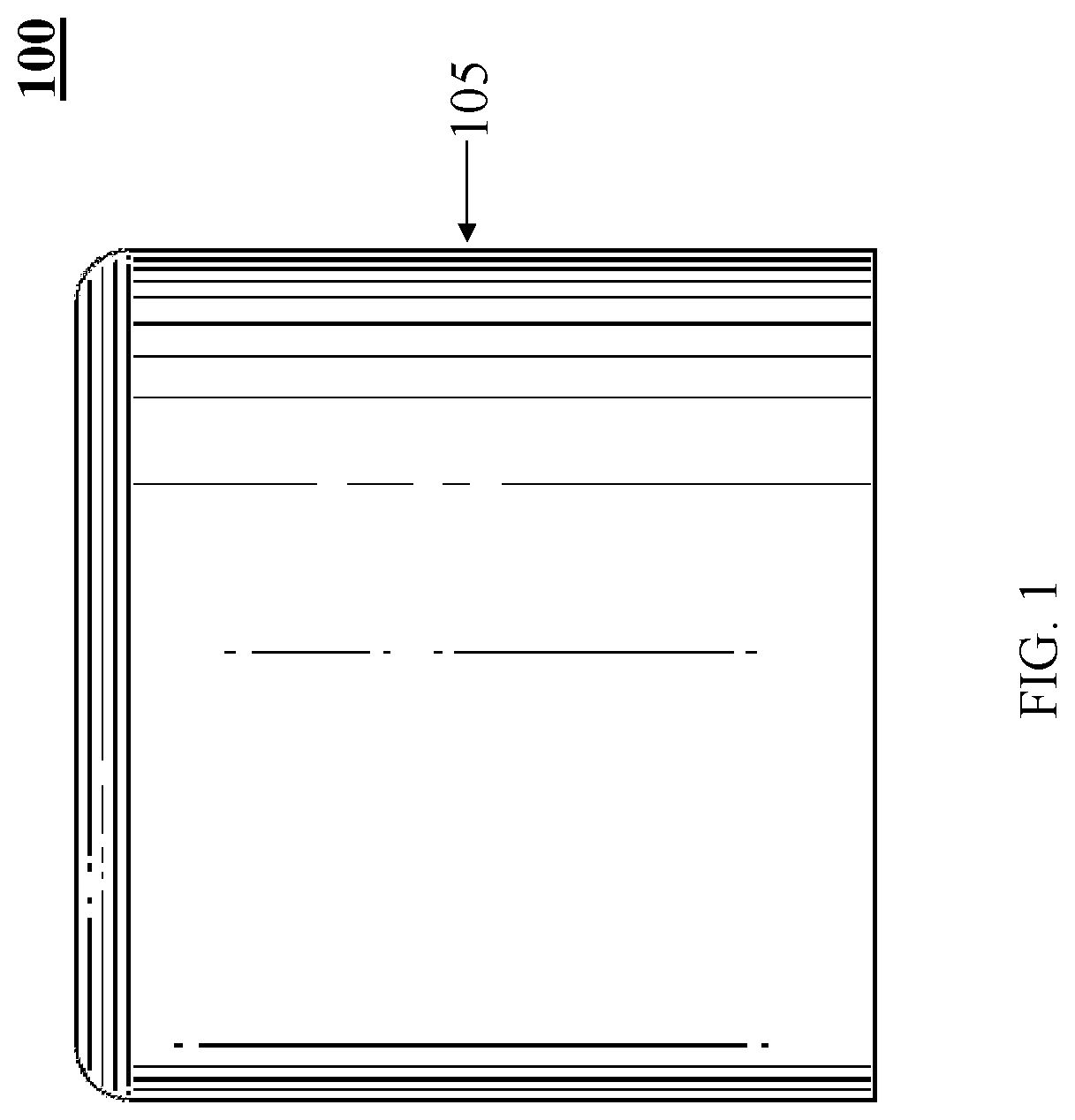
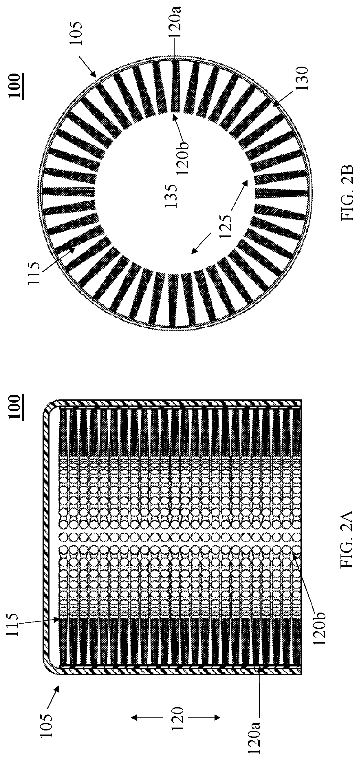
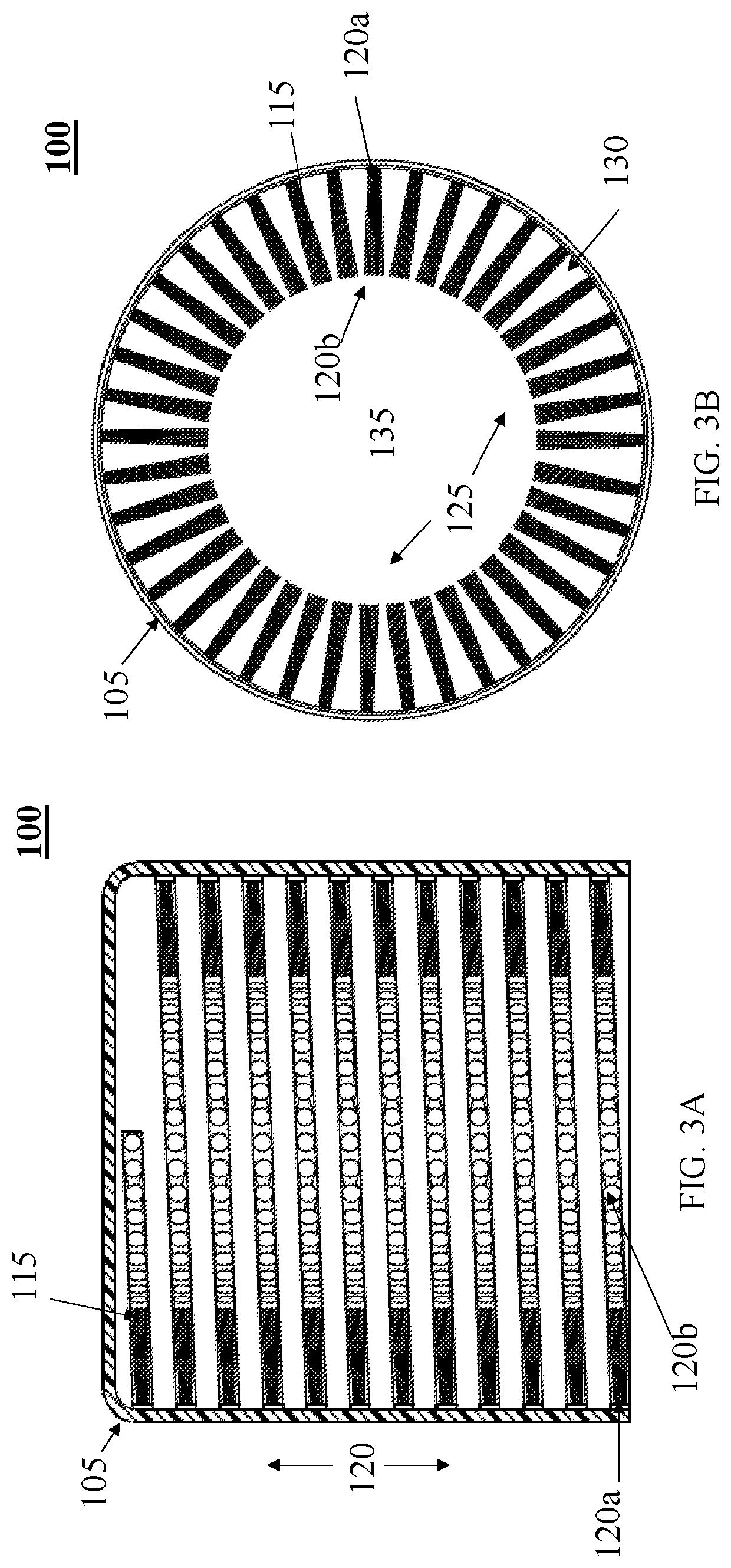
[0038]The present disclosure provides for a cleaning mechanism, assembly, and method for cleaning spray and aerosol nozzles. FIG. 1-FIG. 10B are representative of one embodiment of the present disclosure where a cap for a canister is be configured with a cleaning mechanism inside of the cap. In such an embodiment, the cleaning mechanism is fixed and is not removable. This may be achieved by manufacturing the cap to inherently contain the cleaning mechanism, such as by 3D printing, injection molding, or any other known manufacturing process. In the alternative, the cleaning mechanism may be permanently affixed to the cap after manufacturing using a glue, epoxy, or other adhesive material.

[0039]Referring first to ...


PUM


Abstract

A cleaning mechanism for spray and aerosol nozzles comprising a cap and a plurality of cleaning members where the cleaning members are affixed to the internal surface of the cap in one or more different arrangements covering at least a portion of each of the vertical height of the internal surface and the internal circumference. The cleaning mechanism may be configured as fixed within a cap or as a standalone cap attachment that is inserted and/or detached from the cap for use. The cleaning members may comprise brush members, plastic members, or members made of other materials.

Description

CROSS REFERENCE TO RELATED APPLICATIONS[0001]This application claims priority under 35 U.S.C. § 119(e) to U.S. Provisional Patent Application No. 62 / 817,088 filed on Mar. 12, 2019, entitled “Sprayer Cleaning Mechanism and Method,” which is hereby incorporated by reference in its entirety.BACKGROUND[0002]Canisters are commonly used to house various types of liquids and gels such as toiletries, paints, cleaners, cosmetics, cooking oils, chemicals, and other materials. These liquids are then expelled through one or more nozzles, such as a spray or aerosol, when a user presses an actuator. This design is commonly used in a variety of different industries for both consumer and industrial products due to its ease of use, low cost, and suitability for a wide variety of different liquids.[0003]Each time a liquid is expelled, some of the liquid remains on the outside of the nozzle. Over time, this liquid builds up and hardens, forming a residue that partially or completely blocks or obstruct...

Claims


Application Information

Patent Timeline
Patent Type & Authority Applications(United States)
IPC IPC(8): B65D83/34B65D83/28B65D83/20
CPCB65D83/28B65D83/205B65D83/34B65D83/40B05B15/52
Inventor JANCISIN, DEREK S.
Owner JANCISIN DEREK S
Why Eureka
Try Eureka