Keyboard sensor systems and methods

Pending Publication Date: 2020-10-08
SONUUS
View PDF12 Cites 16 Cited by
  • Summary
  • Abstract
  • Description
  • Claims
  • Application Information

AI Technical Summary

Benefits of technology

[0044]Preferably, but not essentially, the electrically reactive element comprises a passive tuned resonant circuit tuned to a frequency at which the active tuned resonant circuit is driven, thus the position sensor is operated at a single resonant frequency. Advantages to this approach include: Firstly, a larger effective sensing distance can be achieved for a given size of position sensor. Secondly, a larger variation in the output signal of the position sensor for a given variation in sensed position can be obtained, often removing the requirement of an output amplifier for the position sensor and thus reducing complexity and cost. Thirdly, operation of a plurality of proximally located position sensors is facilitated because the inventors have found that a passive tuned resonant circuit of a first position sensor tuned to the resonant frequency of the first position sensor does not substantially affect the output of a second position sensor if the second position sensor is tuned to a significantly different resonant frequency to that of the first position sensor.
[0045]In broad terms an example range of resonant frequencies is 1-10 MHz, balancing speed against the deleterious effect of parasitics. For example a first resonant frequency may be in the range 3-4 MHz and a second resona

Problems solved by technology

Such a multiplexing method combined with connection jitter of the switches, also known as switch bounce, limits the speed at which the switches' connection and disconnection points can be detected.
In some cases the connection and disconnection of the switches can be felt by the musician, which is highly undesirable.
In other cases the switches can become unreliable due to mechanical wear unless high-reliability switches are used, but such switches are expensive.
Such variations are very difficult to remove by a calibration procedure because variation also occurs on an individual key when the key is actuated repeatedly.
Furthermore, it is not possible to change the point during the movement of the key at which a switch connects and disconnects without a mechanical change.
Such a polyphonic aftertouch system is expensive because a separate pressure sensor is used for each individual key.
Alternative detection methods for musical keyboards are known which overcome many of the limitations of mechanical switches and pressure sensors, however these all still have undesirable properties.
However the performance of such systems is vulnerable to degradation by contamination and they need to be

Method used


Image

  • Keyboard sensor systems and methods
  • Keyboard sensor systems and methods
  • Keyboard sensor systems and methods

Examples


Example

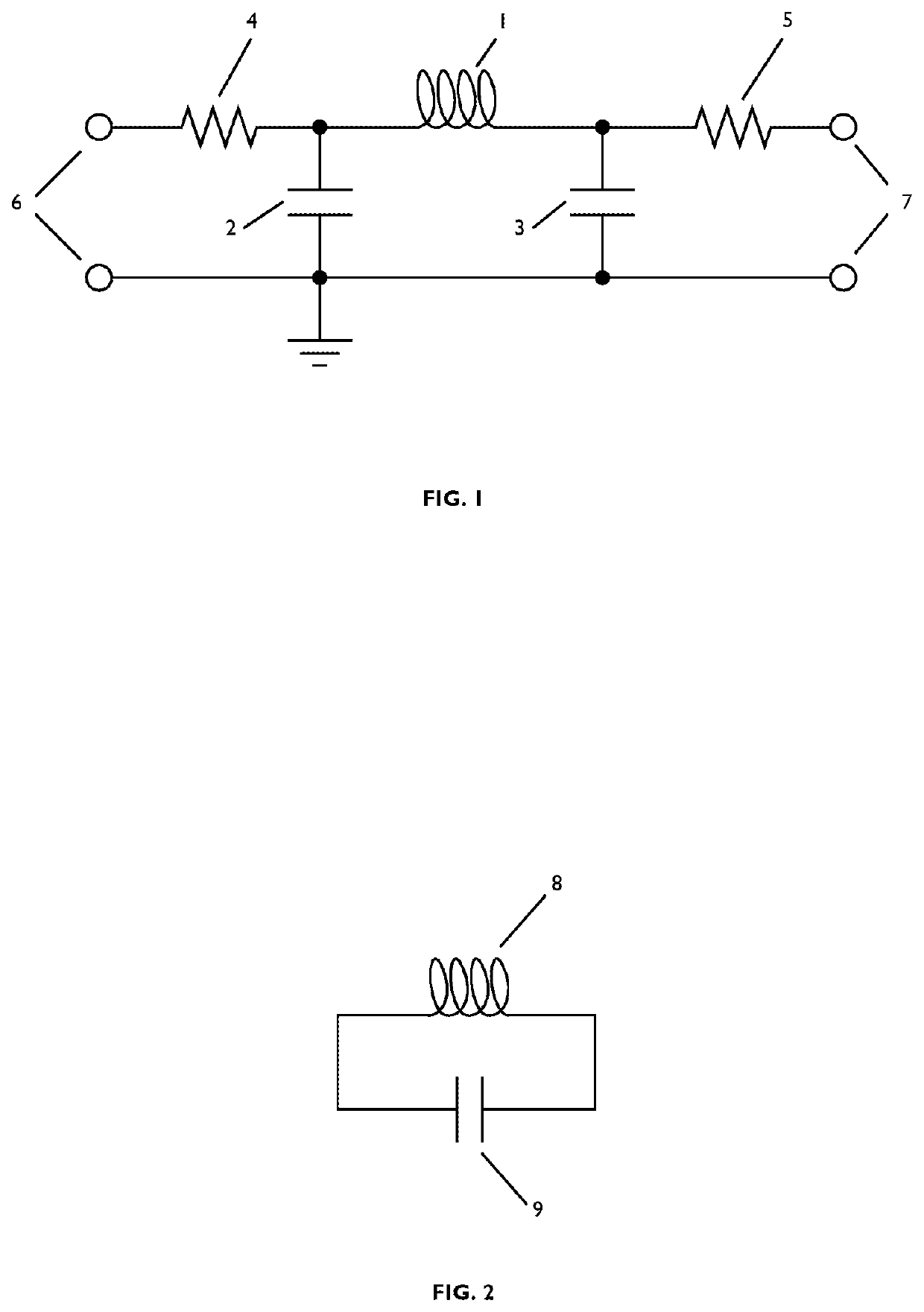
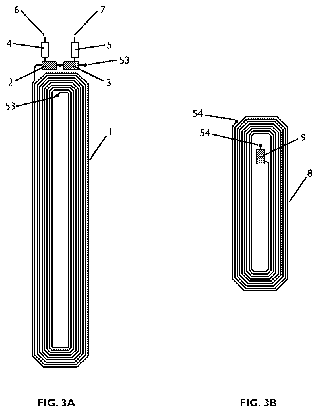
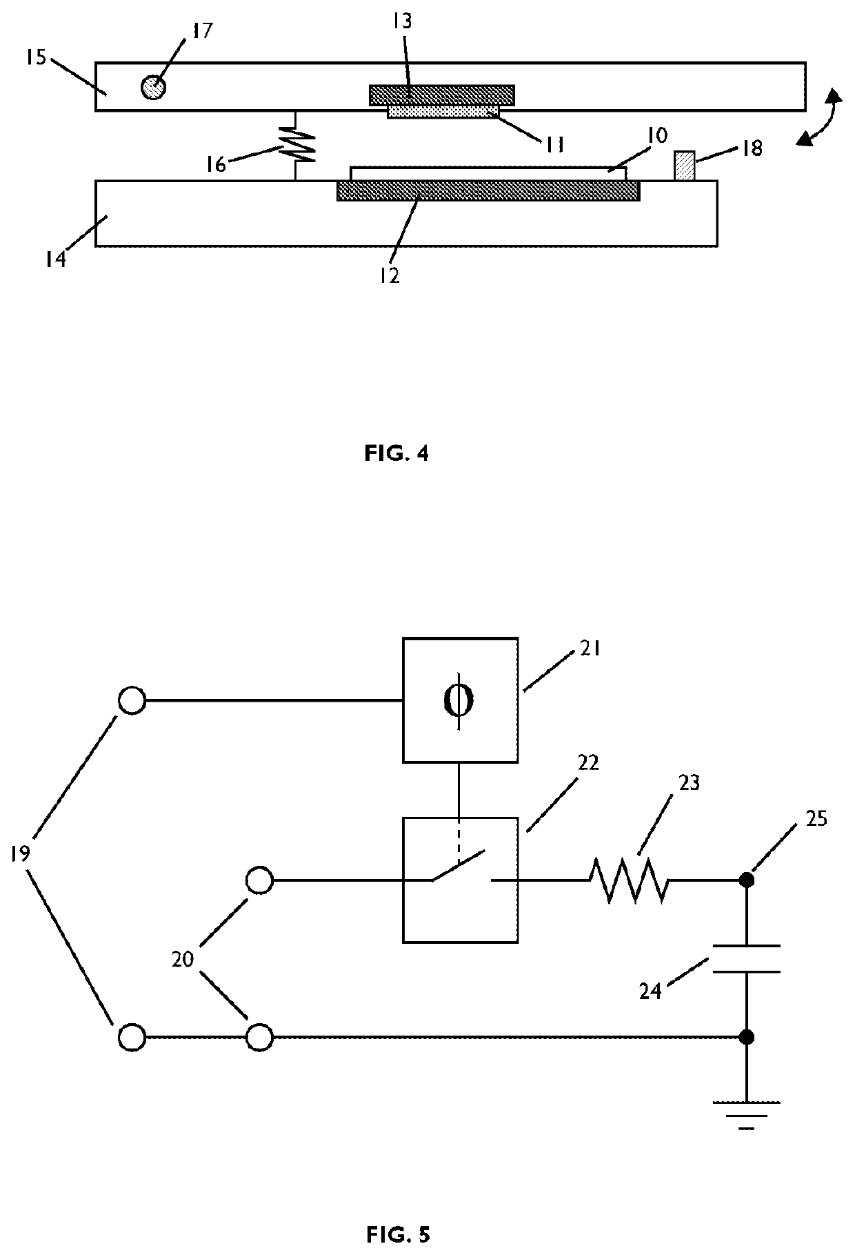
[0064]A preferred embodiment comprises a musical keyboard with a plurality of moveable keys wherein each moveable key FIG. 4 comprises: a moveable top member 15 that is rotated about a pivot point 17 and which resists movement by means of a spring 16 or other mechanical linkage; a fixed bottom member 14; a deformable end-stop 18 which limits movement of said top member; and a position sensor comprising an active tuned resonant circuit 10 inductively coupled to an electrically reactive element 11, henceforth referred to as the target, providing a signal which varies as the mutual separation of said active tuned resonant circuit and said target is varied, drive electronics connected to said active tuned resonant circuit and read-out electronics connected to said active tuned resonant circuit.

[0065]The active tuned resonant circuit FIG. 1 comprises an input resistive element 4, a coil 1, two capacitive elements 2 and 3, an output resistive element 5, a means of connecting 6 drive elect...


PUM


Abstract

A sensing system for a keyboard. Each key sensor comprises passive and active resonant circuits. The passive resonant circuit has a resonant frequency and the active resonant circuit excites the passive resonant circuit at the resonant frequency. A sensor driver drives the active resonant circuit with an RF drive signal, a multiplexing system multiplexes the drive signal such that simultaneously driven key sensors are separated by at least (k−1) keys, and a detector detects a level of RF signal from a driven key sensor for sensing a position and/or velocity of a key.

Description

FIELD OF THE INVENTION[0001]The invention relates to sensing systems and methods for keyboards such as musical instrument keyboards.BACKGROUND[0002]The applicant has previously described resonant circuit-based sensors in GB2494230A.[0003]Musical keyboards for electronic instruments generally use a mechanical switch or similar contacting device to sense a single striking position of a key wherein the closing of the switch is used to detect a note-on event and the opening of the switch is used to detect a note-off event. More sophisticated versions of such instruments may use a plurality of such switches.[0004]Using mechanical sensors such as switches to sense the position of a key on a musical keyboard has many disadvantages. Most musical keyboards feature a large number of keys, typically from 21 to 88 keys. To support such a large number of keys the switches are commonly time-interleaved using a multiplexing method. Such a multiplexing method combined with connection jitter of the ...

Claims


Application Information

Patent Timeline
IPC IPC(8): G10H1/055G10H1/34G10H1/18H03K17/972
CPCG10H1/0555G10H2220/221H03K17/972G10H2220/271G10H1/344G10H1/182G10H2220/275H03K2017/9706G10H1/055H03K17/967G01D5/2073
Inventor CLARK, JAMES HASTINGSMCAULIFFE, JOHN MICHAEL
Owner SONUUS
Why Eureka
Try Eureka