Blood pressure measuring device

a measuring device and blood pressure technology, applied in horology, instruments, angiography, etc., can solve problems such as affecting the reducing accuracy of blood pressure measurement results, so as to suppress the effect of suppressing the generation of wrinkles and folds

Active Publication Date: 2020-10-15
OMRON HEALTHCARE CO LTD +1
View PDF7 Cites 0 Cited by
  • Summary
  • Abstract
  • Description
  • Claims
  • Application Information

AI Technical Summary

Benefits of technology

[0020]According to this aspect, the strap and the curler deform in a direction in which the strap and the curler come into contact with the wrist by making the thickness of the cuff in the inflating direction be larger than those of the pressing cuff and the sensing cuff. Therefore, the strap and the curler come into close contact with the portion of the wrist between the dorsal side and the palmar side, and the skin of the wrist between the dorsal side and the palmar side is pulled. Thus, the skin of the wrist on the palmar side facing the sensing cuff is stretched, and the strap and the curler on the palmar side are pulled. As a result, the sensing cuff is in suitably close contact with the surface of the wrist on the palmar side, making it possible to further suppress the generation of wrinkles and folds in the sensing cuff.
[0021]The present invention can provide a blood pressure measuring device capable of suppressing the generation of wrinkles and folds in a sensing cuff.

Problems solved by technology

Such a blood pressure measuring device has a drawback in that the accuracy of the results of blood pressure measurement decreases when wrinkles, folds, or the like are generated in the cuff whose pressure is to be detected using a pressure sensor. FIG. 23 shows an example of a cross-sectional image in which a blood pressure measuring device is worn on a wrist and a cuff is inflated.
In the example shown in FIG. 23, when the blood pressure measuring device is worn on the wrist, wrinkles and folds are generated in the cuff so as to form a deep groove, and may divide the inner space of the cuff, as indicated by a portion X. In particular, as the cuff becomes smaller due to the downsizing of the blood pressure measuring device, the accuracy of the results of measurement of blood pressure may decrease.
A wearable device does not only pose problems when used for blood pressure measurement.
It also poses problems when used, for example, as a biological information measuring device for the measurement of a pulse, etc., in that it cannot accurately measure a pulse.
In the blood pressure measuring device, however, when the cuff is brought into close contact with a wrist by adjusting the pulling force of each strap, the cuff is partially pressed against the wrist, the device main body, and the like, and wrinkles or folds are likely to be generated in the cuff.
If the pressure distribution varies, correct pressure cannot be measured, and the extent of error in measurement results may increase.

Method used


Image

  • Blood pressure measuring device
  • Blood pressure measuring device
  • Blood pressure measuring device

Examples


first embodiment

[0045]Hereinafter, an example of a blood pressure measuring device 1 according to a first embodiment of the present invention will be described with reference to FIGS. 1 to 15.

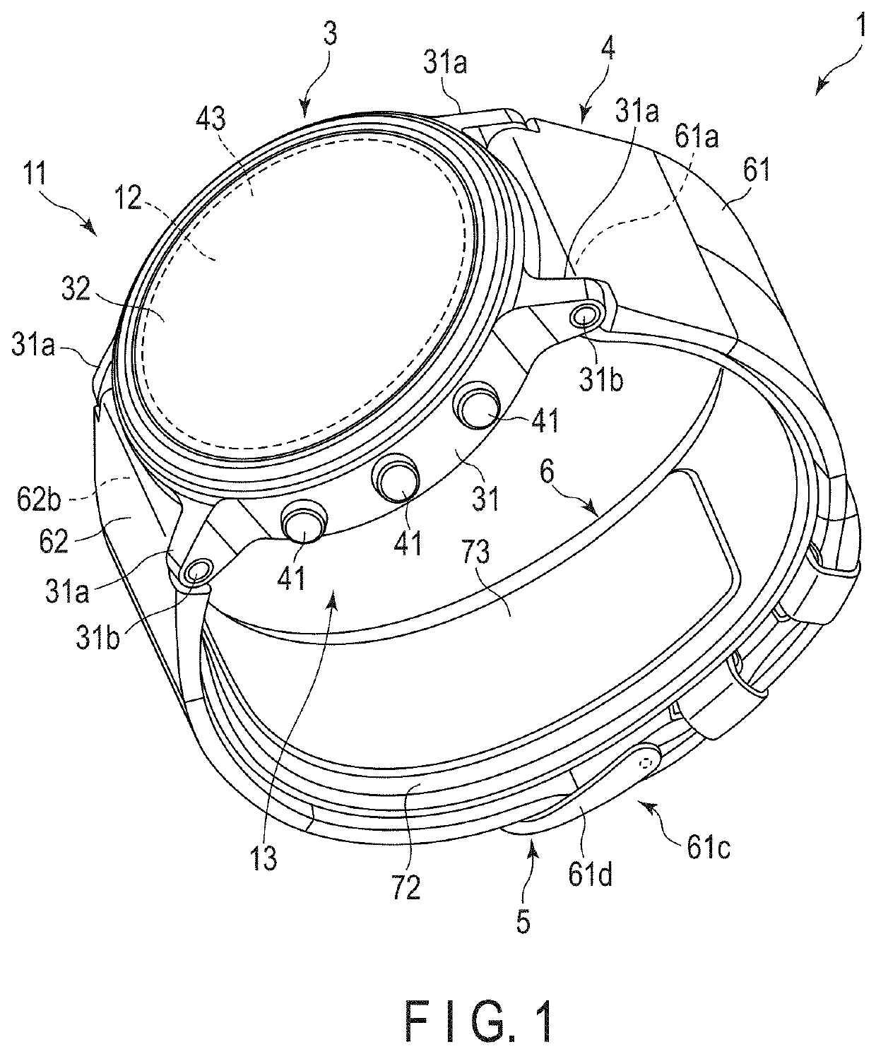
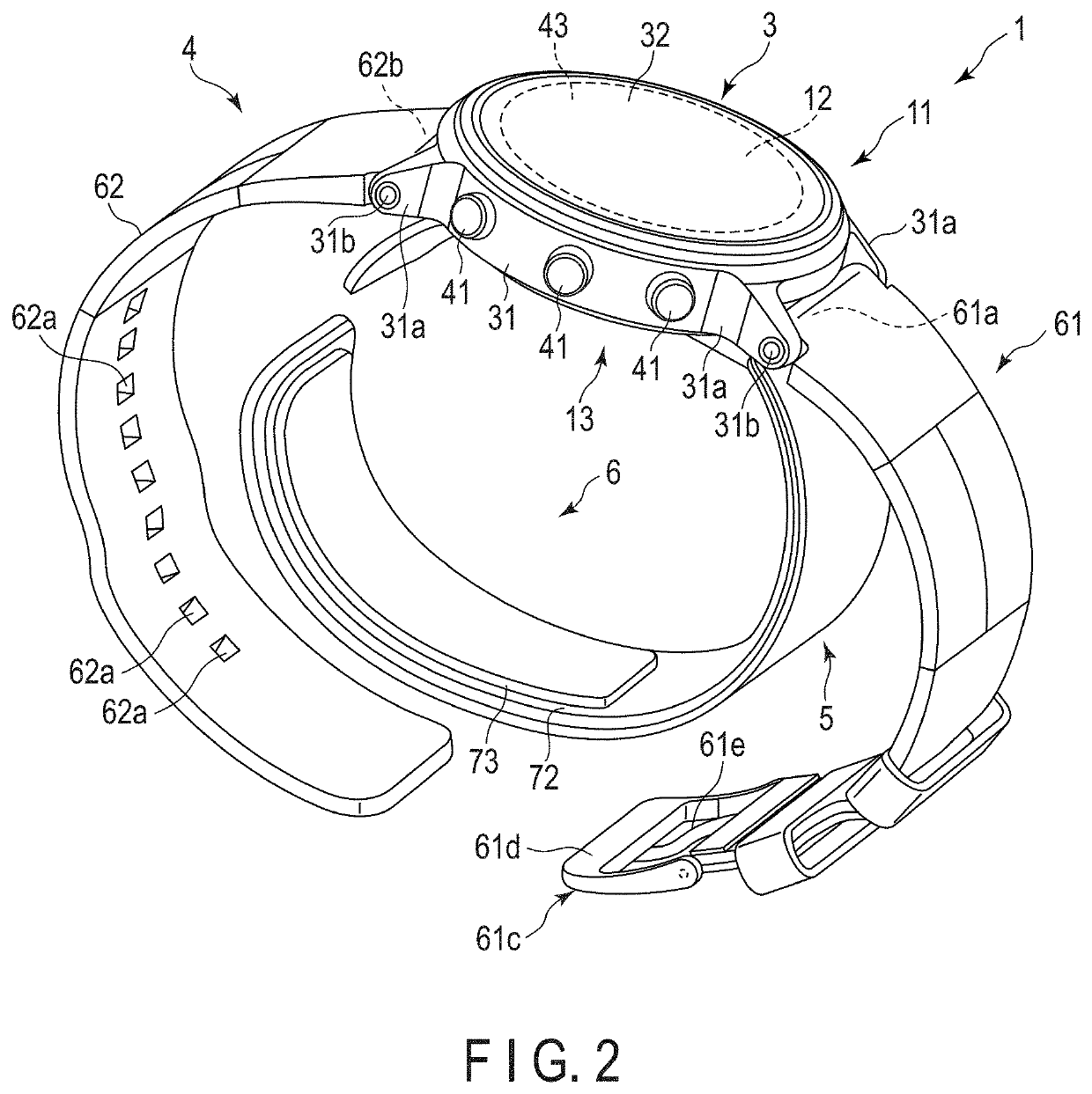
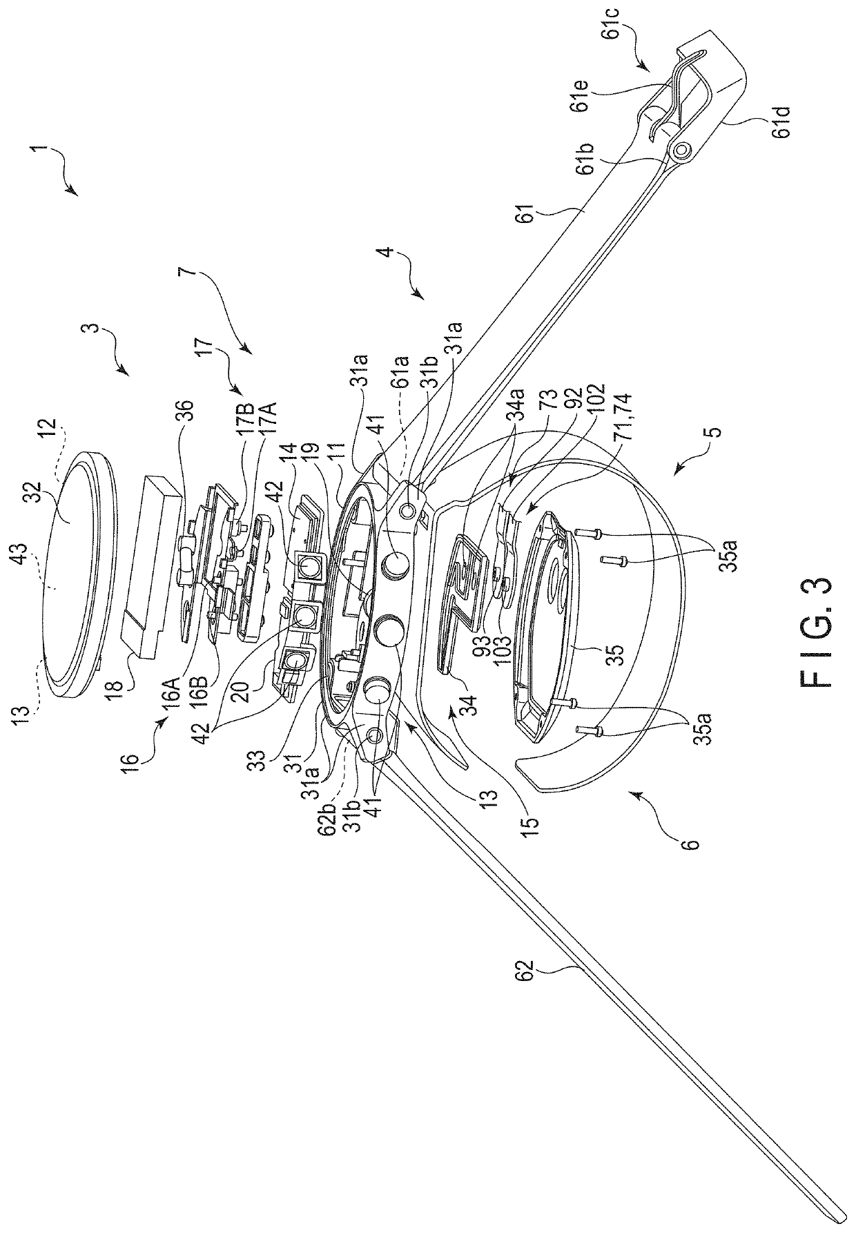
[0046]FIG. 1 is a perspective view of a configuration of the blood pressure measuring device 1 according to the first embodiment of the present invention with a strap 4 closed. FIG. 2 is a perspective view of a configuration of the blood pressure measuring device 1 with the strap 4 opened. FIG. 3 is an exploded view of a configuration of the blood pressure measuring device 1. FIG. 4 is an explanatory diagram showing a state in which the blood pressure measuring device 1 is worn on a wrist. FIG. 5 is a block diagram showing a configuration of the blood pressure measuring device 1. FIG. 6 is a perspective view of configurations of a device main body 3 and a curler 5 of the blood pressure measuring device 1. FIG. 7 is a perspective view of a configuration of the device main body 3 of the blood pressure measuring ...

second embodiment

[0130]Next, a second embodiment of the blood pressure measuring device 1 will be described with reference to FIGS. 20 to 22. The blood pressure measuring device 1 does not include the flat plate 75 in the cuff structure 6. That is, the configuration of the second embodiment is achieved by removing the flat plate 75 from the configuration of the blood pressure measuring device 1 of the first embodiment described above; therefore, part of the configuration of the present embodiment identical to that of the blood pressure measuring device 1 of the first embodiment will be described using the same reference numerals, and the descriptions and figures thereof will be omitted as appropriate.

[0131]The blood pressure measuring device 1 according to the second embodiment exhibits the same effects as those of the blood pressure measuring device 1 according to the first embodiment, except those exhibited by the flat plate 75, and can suppress the generation of wrinkles and folds in the sensing ...


PUM


Abstract

A blood pressure measuring device includes a device main body; a curler configured to bend along a circumferential direction of a wrist of a living body, including one end and another end separated from each other, also configured to come into contact with a portion of the wrist at least between a dorsal side and a palmar side; a strap provided to the device main body; a sensing cuff arranged in a region of the wrist where arteries exist; a back plate provided between the curler and the sensing cuff and extending in a circumferential direction of the wrist; a pressing cuff provided on a side of the curler nearer to the strap and configured to press the sensing cuff; and a cuff provided on a side of the curler nearer to the living body and arranged on the dorsal side of the wrist.

Description

CROSS-REFERENCE TO RELATED APPLICATIONS[0001]This is a Continuation Application of PCT application No. PCT / JP2018 / 046232, filed Dec. 17 2018, which was published under PCT Article 21(2) in Japanese.[0002]This application is based upon and claims the benefit of priority from Japanese Patent Application No. 2017-252917, filed Dec. 28, 2017, the entire contents of which are incorporated herein by reference.BACKGROUNDField[0003]The present invention relates to a blood pressure measuring device for the measurement of blood pressure.Description of the Related Art[0004]In recent years, a blood pressure measuring device for the use of blood pressure measurement has been utilized not only in medical facilities but also in households as a means to confirm health condition. A blood pressure measuring device measures blood pressure by detecting vibrations of an arterial wall, by, for example, wrapping a sensing cuff around an upper arm, a wrist, or the like of a living body, inflating and defla...

Claims


Application Information

Patent Timeline
Patent Type & Authority Applications(United States)
IPC IPC(8): A61B5/021A61B5/022A61B5/00A61B5/0235
CPCA61B2562/02A61B5/681A61B5/0235A61B5/02141A61B5/02225A61B5/0225A61B5/02438A61B5/7455A61B2562/0219A61B5/1118A61B5/002A61B5/02241G04G21/025G04G17/04G04G21/04
Inventor HAMAGUCHI, TAKEHIROKUBO, TAKESHISANO, YOSHIHIKONISHIOKA, TAKANORIMORI, KENTAROHIGASHIMURA, YU
Owner OMRON HEALTHCARE CO LTD
Why Eureka
Try Eureka