Motor rotor and permanent magnet motor

a permanent magnet motor and rotor technology, applied in the field of motors, can solve the problems of inability to ensure the efficiency of the permanent magnet motor at high frequency and low frequency simultaneously, the inability to adjust the internal magnetic field of the motor, and the limited maximum operating frequency of the motor, so as to reduce the difficulty of magnetization and demagnetization of the motor, reduce the effect of magnetization and demagnetization current and large reduction of coercivity

Active Publication Date: 2020-10-15
GREE ELECTRIC APPLIANCES INC
View PDF0 Cites 3 Cited by
  • Summary
  • Abstract
  • Description
  • Claims
  • Application Information

AI Technical Summary

Benefits of technology

[0006]Therefore, the technical problem to be solved by the invention is to provide a motor rotor and a permanent magnet motor, which can effectively reduce the magnetizing and demagnetizing difficulty, increase the magnetizing range of the motor and improve the operating efficiency of the motor when the motor is subjected to a flux intensifying control.
[0027]The motor rotor provided by the invention comprises a rotor core and a plurality of magnetic poles provided in the rotor core, wherein the magnetic pole comprises a first permanent magnet, a second permanent magnet and a third permanent magnet, the first permanent magnet being arranged at a central position of the magnetic pole where the first permanent magnet is located, the second permanent magnet being arranged at two sides of the first permanent magnet, the third permanent magnet being arranged at one side, far away from the first permanent magnet, of the second permanent magnet, and the coercivity of the first permanent magnet being lower than that of the second permanent magnet and the third permanent magnet, the third permanent magnet being arranged on the q axis of the motor. According to the motor rotor, when the motor operates, the magnetic steel with low coercivity always operates in a flux intensifying state, the problem of magnetic flux change does not occur. Since the first permanent magnet with low coercivity is located at the center of the magnetic pole where the first permanent magnet is located, the magnetization and demagnetization difficulty of the motor can be reduced, the magnetization and demagnetization current of the permanent magnet with low coercivity is greatly reduced, and the magnetic stability of the permanent magnet with low coercivity in the rotor during normal operation is improved. Since the third permanent magnet is arranged on the q axis of the motor, the reluctance on the q axis of the motor can be increased, the inductance Ld>Lq is guaranteed, and the operating efficiency of the motor is optimal under the flux intensifying state.

Problems solved by technology

Therefore, the internal magnetic field of the motor cannot be adjusted, and the efficiency of the permanent magnet motor at high frequency and low frequency cannot be assured simultaneously.
Besides, given that the power supply has constant voltage, the highest operating frequency of the motor is limited.
Therefore, a heretofore unaddressed need exists in the art to address the aforementioned deficiencies and inadequacies.

Method used


Image

  • Motor rotor and permanent magnet motor
  • Motor rotor and permanent magnet motor
  • Motor rotor and permanent magnet motor

Examples


first embodiment

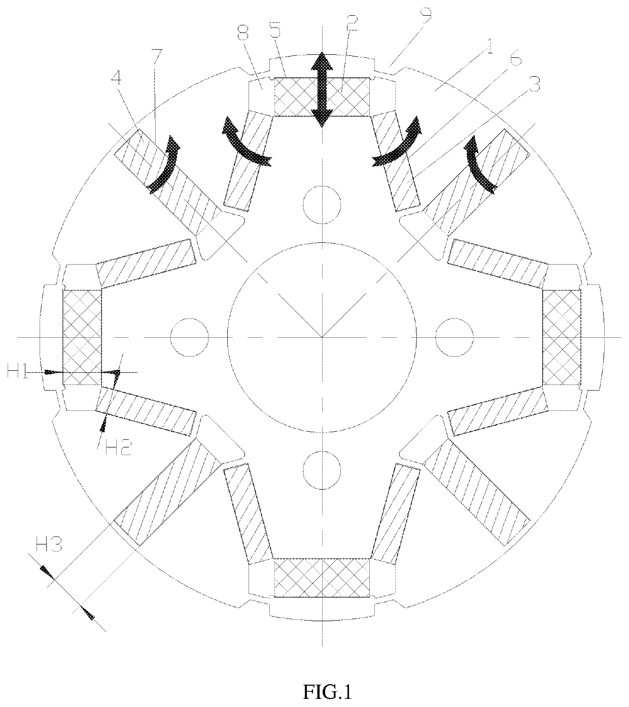
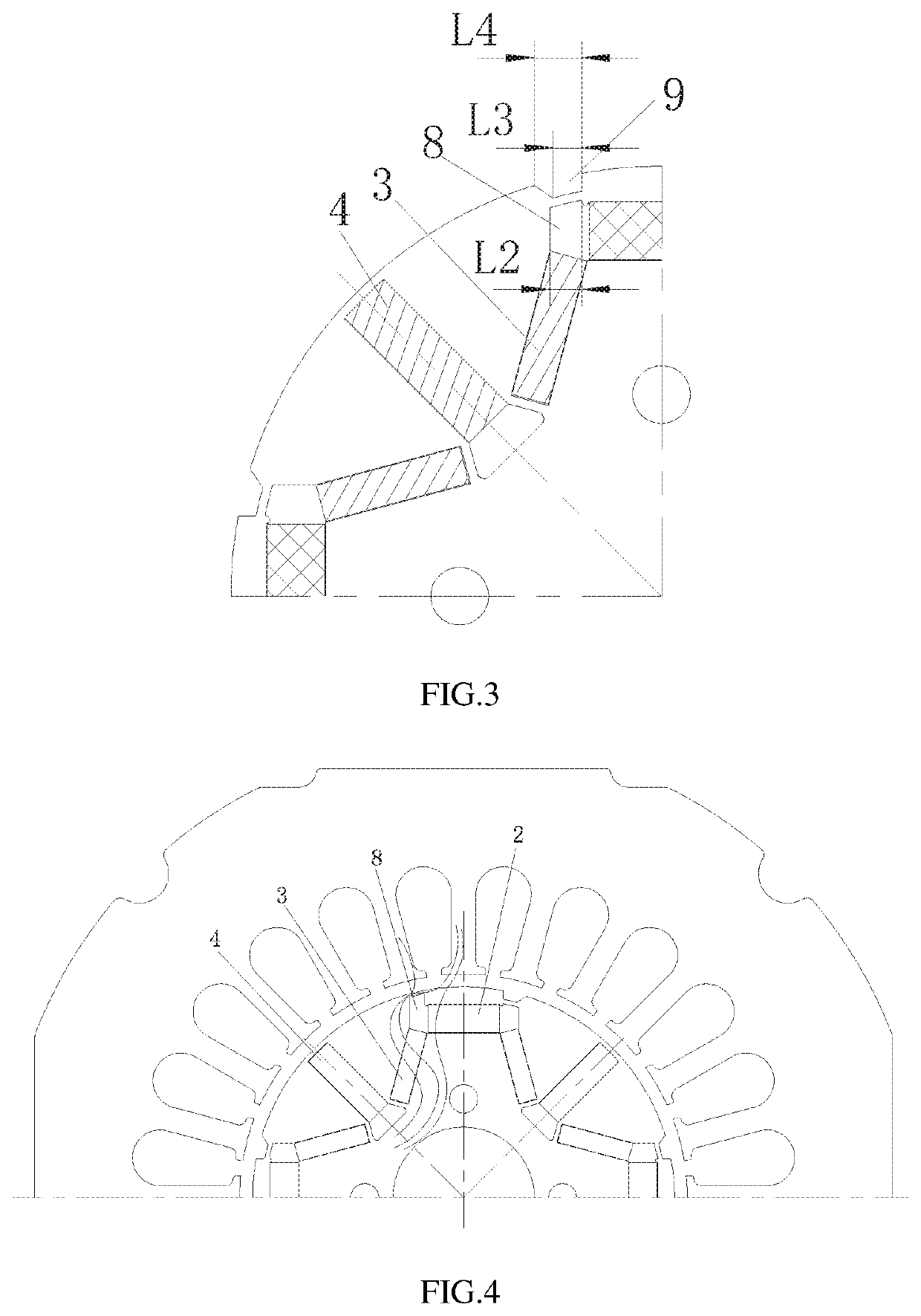
[0047]Referring to FIGS. 1 to 5 in combination, according to the present disclosure, both ends of the first permanent magnet 2 are provided with a first flux barrier slot 8 located at radial outer side of the second permanent magnet 3. The first flux barrier slots 8 are arranged at the both ends of the first permanent magnet 2 along the circumferential direction, so that the difficulty of magnetizing and demagnetizing the magnetic steel during magnetic modulation can be reduced, the magnitude of magnetizing and demagnetization current of the motor during magnetic modulation can be reduced. Therefore, the problem that demagnetizing is likely to occur when the permanent magnet with low coercivity is influenced by the permanent magnet with high coercivity is avoided or reduced. The flux adjustment range of the motor is increased, the magnetic stability of the permanent magnet with low coercivity in the rotor during normal operation is improved, and the power required for the motor oper...

second embodiment

[0054]Referring to FIGS. 6 and 7 in combination, according to the present disclosure, a rotor core 1 includes a second mounting slot 6, second permanent magnet 3 is arranged in the second mounting slot 6, and a flux bridge 10 is provided between the first flux barrier slot 8 and the second mounting slot 6. In the cross section of the rotor core 1, the width of the flux bridge 10 is L5, and the thickness of a unilateral air gap of the motor is L, where L5.

[0055]Under the normal state of the variable flux motor, the magnetism of the second permanent magnet 3 and third permanent magnet 4 with higher coercivity will press the magnetism of the first permanent magnet 2 with lower coercivity, so that the second permanent magnet 3 and third permanent magnet 4 with higher coercivity have a demagnetization effect on the first permanent magnet 2 with lower coercivity. In normal state, the first permanent magnet 2 with lower coercivity has a risk of demagnetization. Meanwhile, during the magnet...

third embodiment

[0058]Referring to FIGS. 8 and 9 in combination, according to the present disclosure, the rotor core 1 further includes a second flux barrier slot 11 extending from an end, close to an end of the first flux barrier slot 8, of the second mounting slot 6 toward the d axis of the motor.

[0059]Preferably, the rotor core 1 further comprises a third flux barrier slot 12 and a first mounting slot 5. The first permanent magnet 2 is arranged in the first mounting slot 5, the third flux barrier slot 12 is located on the radial inner side of the first mounting slot 5 and is arranged on the d axis of the motor, and the third flux barrier slot 12 is located between the two second flux barrier slots 11. The second flux barrier slot 11 is additionally arranged at one side, close to the d axis of the motor, of the second mounting slot 6, so that the direction of the magnetic lines of the second permanent magnet can be adjusted, more magnetic lines are used for changing the magnetism of the first per...


PUM

PropertyMeasurementUnit
included angleaaaaaaaaaa
coercivityaaaaaaaaaa
radial depthaaaaaaaaaa

Abstract

The present invention discloses a motor rotor and a permanent magnet motor. The motor rotor includes a rotor core and a plurality of magnetic poles provided in the rotor core, wherein each magnetic pole includes a first permanent magnet, a second permanent magnet and a third permanent magnet; the first permanent magnet being arranged on a central position of the magnetic pole on which said first permanent magnet is located, the second permanent magnet being arranged at two sides of the first permanent magnet, the third permanent magnet being arranged at one side of the second permanent magnet far away from the first permanent magnet; the coercivity of the first permanent magnet is smaller than that of the second permanent magnet and that of the third permanent magnet; and the third permanent magnet is arranged on a q axis of the motor.

Description

CROSS-REFERENCE TO RELATED APPLICATIONS[0001]This application is a national stage application of PCT Application No. PCT / CN2018 / 112311. This Application claims priority from PCT Application No. PCT / CN2018 / 112311, filed Oct. 29, 2018, and CN Application No. 201711388513.4, filed Dec. 21, 2017, the contents of which are incorporated herein in the entirety by reference.[0002]Some references, which may include patents, patent applications, and various publications, are cited and discussed in the description of the present disclosure. The citation and / or discussion of such references is provided merely to clarify the description of the present disclosure and is not an admission that any such reference is “prior art” to the disclosure described herein. All references cited and discussed in this specification are incorporated herein by reference in their entireties and to the same extent as if each reference was individually incorporated by reference.TECHNICAL FIELD[0003]The present disclo...

Claims


Application Information

Patent Timeline
Patent Type & Authority Applications(United States)
IPC IPC(8): H02K1/27H02K3/487
CPCH02K1/2766H02K2213/03H02K2201/03H02K3/487
Inventor HU, YUSHENGCHEN, BINZHOU, BOWANG, MINXIAO, YONG
Owner GREE ELECTRIC APPLIANCES INC
Why Eureka
Try Eureka