
Winding machine

Inactive Publication Date: 2020-10-15
ATS WICKEL UND MONTAGETECHN
View PDF0 Cites 4 Cited by
  • Summary
  • Abstract
  • Description
  • Claims
  • Application Information

AI Technical Summary

Benefits of technology

The present invention is about a winding machine that can be used for different winding methods. The machine has interchangeable receiving units and feed units, making it easy to switch between different winding methods. The machine has a gantry that allows for a large displacement range without affecting the winding space. The coil-former receptacle is displaceable, making it simpler to feed winding material. Heating multiple coil formers at the same time increases productivity and allows for testing of conditions in production.

Problems solved by technology

It is therefore not intended or not possible for a machine designed for one method to be used in another method.

Method used


Image

  • Winding machine
  • Winding machine
  • Winding machine

Examples


Embodiment Construction

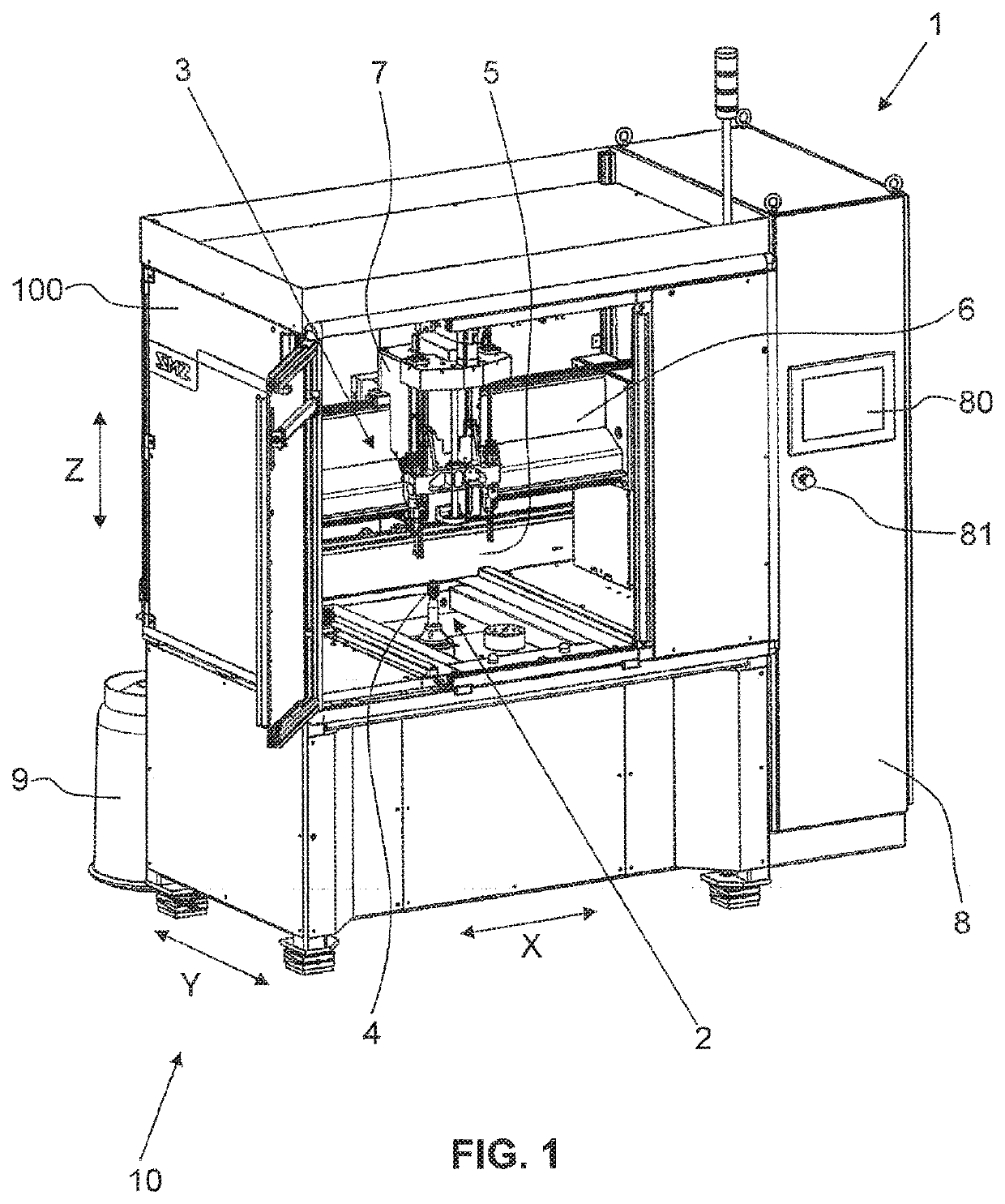
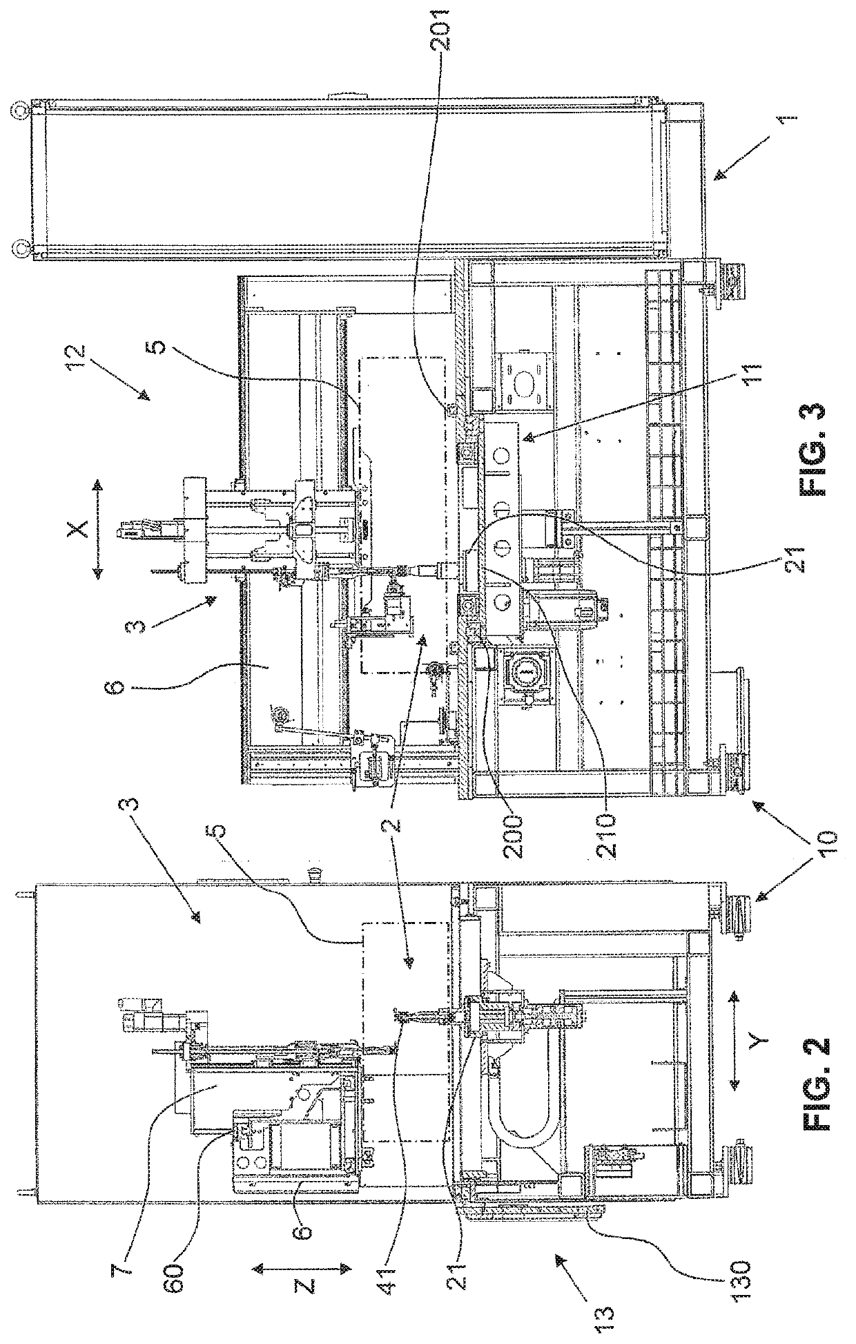
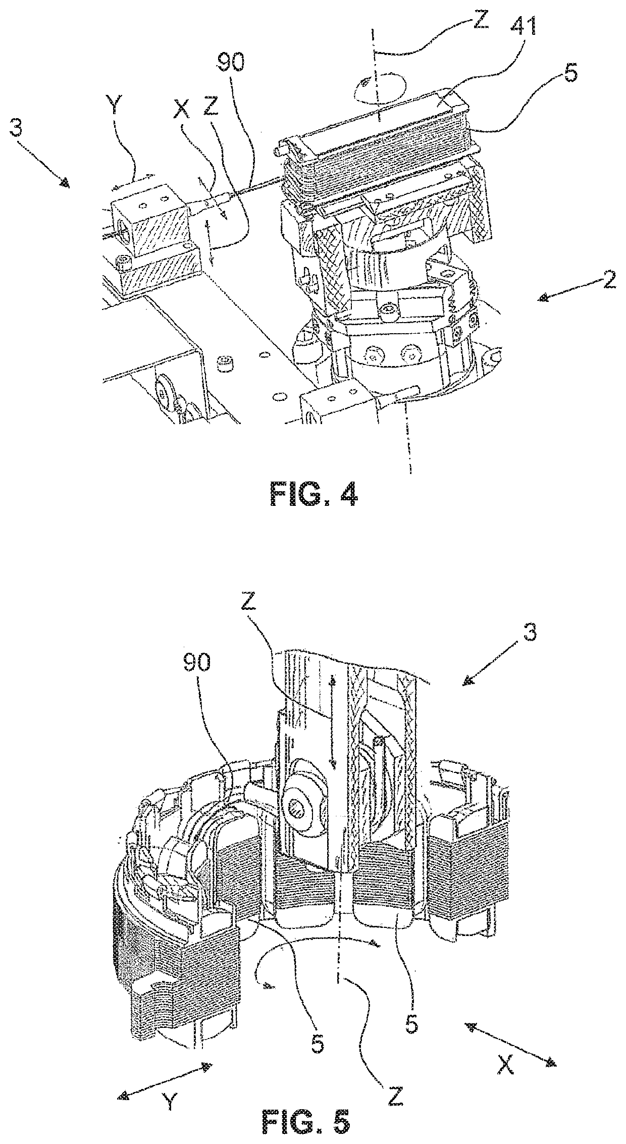
[0057]FIG. 1 shows a perspective view of a winding machine 1 according to the invention. The winding machine 1 substantially has a machine stand 10 having a coil-former receptacle 2 and a winding-material feed 3, wherein the coil-former receptacle 2 is designed to provide a coil former 41, 42 of a coil 4 to be wound in a receiving space 5, and wherein the winding-material feed 3 is designed to feed winding material 90 to the receiving space 5. A gantry 6, on which a slide 7 is arranged such that it is movable in a first direction X, is arranged on the machine stand 10. The winding machine 1 furthermore has a control cabinet 8 for operating and controlling the winding machine 1. An input unit 80 in the form of a touchscreen is provided on the front side of the control cabinet 8. An emergency off button 81 is furthermore provided in the region of the input unit 80. The control cabinet 8 houses a system control. The special feature of the system control is that it is suitable for imple...


PUM


Abstract

A winding machine (1) for winding coils (4), having at least one coil-body receptacle (2) providing a receiving space (5) for coil bodies to be wound and at least one winding-material feed (3) being configured to feed winding material into the receiving space (5). The at least one coil-body receptacle (2) comprises at least a first and a second receiving unit, wherein, in a first setting, using the first receiving unit, the winding machine (1) allows winding in accordance with a first winding technique and wherein, in a second setting, using the second receiving unit, the winding machine (1) allows winding in accordance with a second winding technique different from the first winding technique. The first and second winding techniques are selected from the group of winding techniques consisting of the coil-winding technique, the conventional needle-winding technique, the linear winding technique and the flyer-winding technique.

Description

TECHNICAL FIELD[0001]The present invention relates to the field of winding machines, in particular wire-winding machines, for winding individual coils or coil arrangements, for example for laboratory operations or product development or for pilot lot or small lot production.PRIOR ART[0002]Winding machines for different winding techniques are known from the prior art. In general, all devices which can implement a winding method have a coil-former receptacle, in which a coil former to be wound is received in a receiving space, and a winding-material 15 feed with which winding material can be fed into the receiving space. Known winding techniques are, for example, the coil winding technique, the needle winding technique, wherein the conventional needle winding technique and the linear winding technique both fall under the needle winding technique, and the flyer winding technique.[0003]These winding techniques as understood herein are described in more detail with 20 reference to figure...

Claims


Application Information

Patent Timeline
IPC IPC(8): H02K15/08
CPCH02K15/08H01F41/09H02K15/0435H02K15/095
Inventor RISSI, DANIELULRICH, PETER
Owner ATS WICKEL UND MONTAGETECHN
Learn More