Multi-function nacelles for an aircraft

a multi-functional, aircraft technology, applied in the direction of airflow influencers, aircraft navigation control, efficient propulsion technologies, etc., can solve the problems of offset of the advantages of larger nacelles and increase the yaw moment, so as to reduce air turbulence, increase the lift of the aircraft, and enhance the horizontal propulsive thrust

Active Publication Date: 2020-10-22
WRIGHT ELECTRIC INC
View PDF0 Cites 14 Cited by
  • Summary
  • Abstract
  • Description
  • Claims
  • Application Information

AI Technical Summary

Benefits of technology

[0003]Disclosed herein is an aircraft including a fuselage having a round nose at the front end, a tapered blown pitch flap at the opposite aft end, and a pair of outwardly extending wings. As an important feature of this invention, a pair of rectangular, multi-function nacelles are detachably connected to respective ones of the wings so as to be held entirely above the wings. The nacelles are positioned atop the wings so as to he spaced away from the fuselage and thereby establish air flow paths along the inboard wing between the fuselage and the nacelles by which to reduce air turbulence flowing into the nacelles when the aircraft is in flight.
[0004]Each of the pair of rectangular nacelles has a narrow air intake end, an opposite narrow air exhaust end, and a plurality of electric motors and motor driven fans extending horizontally between the air intake and exhaust ends. Divider walls run horizontally through the nacelle between pairs of the fans and motors to prevent incoming air from spilling between the fans. Each nacelle includes an air flow duct between movable air flow control surfaces that are located at the air intake and air exhaust ends of the nacelle by which to enable the aircraft to be provided with enhanced horizontal propulsive thrust, thrust vectoring and thrust reversing.
[0005]In particular, upper and lower air inlet slats at the air intake end of the nacelle are rotatable downwardly relative to the air flow duct to increase lift of the aircraft during takeoff, Upper and lower air exhaust flaps at the air exhaust end of the nacelle are rotatable upwardly or downwardly relative to the air flow duct to either slow the speed of the aircraft while landing or increase lift during takeoff. An intermediate air exhaust guide that is located between the air flow duct and the upper air exhaust flap of the nacelle is rotatable upwardly relative to the air flow duct to also slow the aircraft during landing. Upper and lower exhaust diverter flaps that are located between the upper and lower air exhaust flaps at the air exhaust end of the nacelle are rotatable relative to the air exhaust flaps to further slow the aircraft during landing or increase lift during takeoff.
[0006]Mounted on the top of the flat tail of the fuselage of the aircraft is a generally rectangular rear boundary layer nacelle. The rear nacelle is located between a pair of turbo generators which are held outwardly from the tail of the fuselage by respective horizontal tail sections. The rear nacelle has a plurality of fans and electric motors extending horizontally therethrough and rotatable yaw vanes located behind the fans and the motors. The rear nacelle and the pair of turbo generators are preferably located behind both the pressure bulkhead and the pressurized passenger cabin of the aircraft to avoid damage to the passenger cabin in the event of a rotor burst.

Problems solved by technology

Consequently, the advantages of larger nacelles are offset, by increased drag and installation constraints.
In addition, when one of the large engines fails, there is an increased yaw moment that is caused by drag on the nacelle, and a large vertical tail and rudder are required to offset the yawing moment.

Method used


Image

  • Multi-function nacelles for an aircraft
  • Multi-function nacelles for an aircraft
  • Multi-function nacelles for an aircraft

Examples


Embodiment Construction

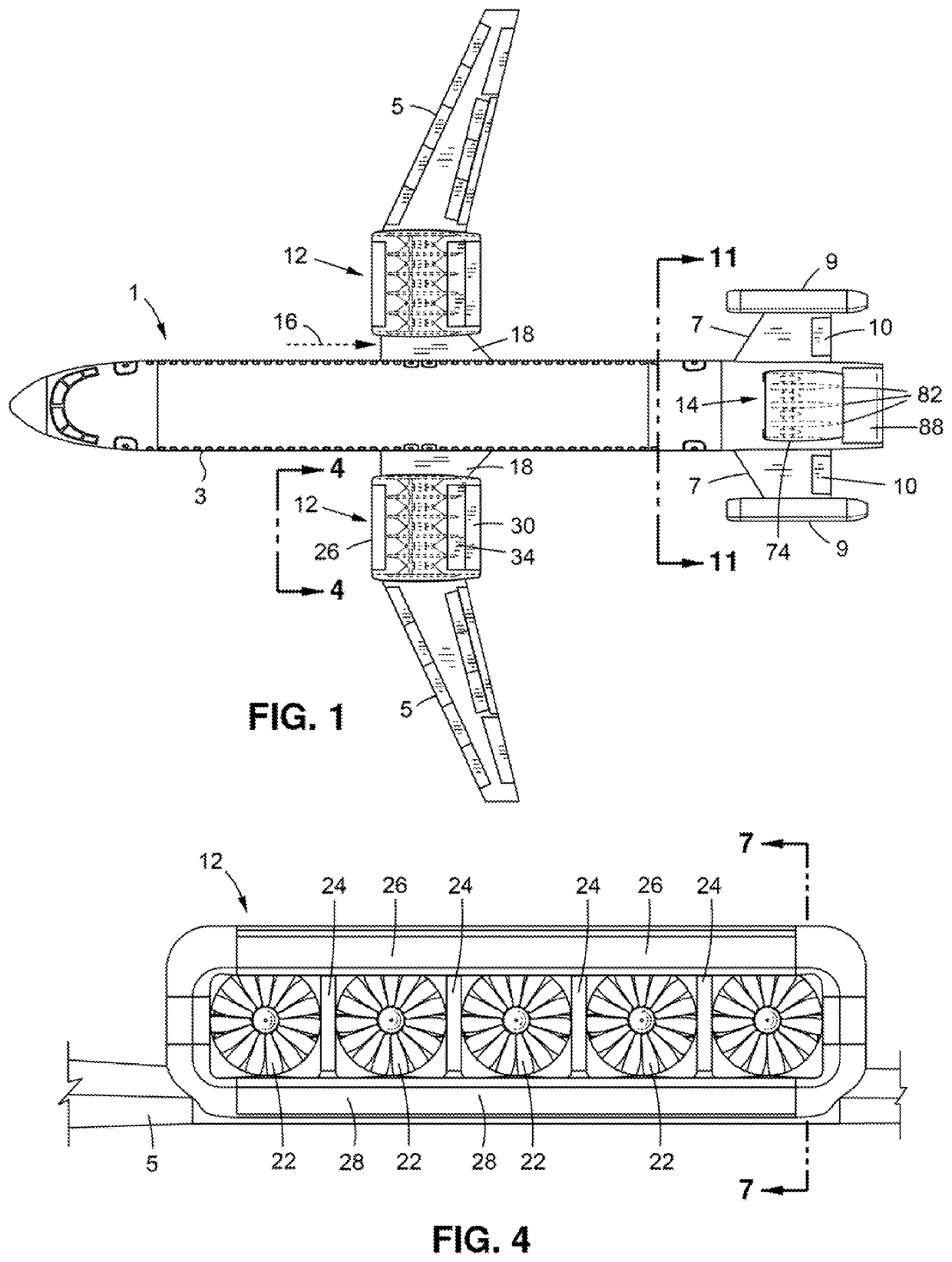
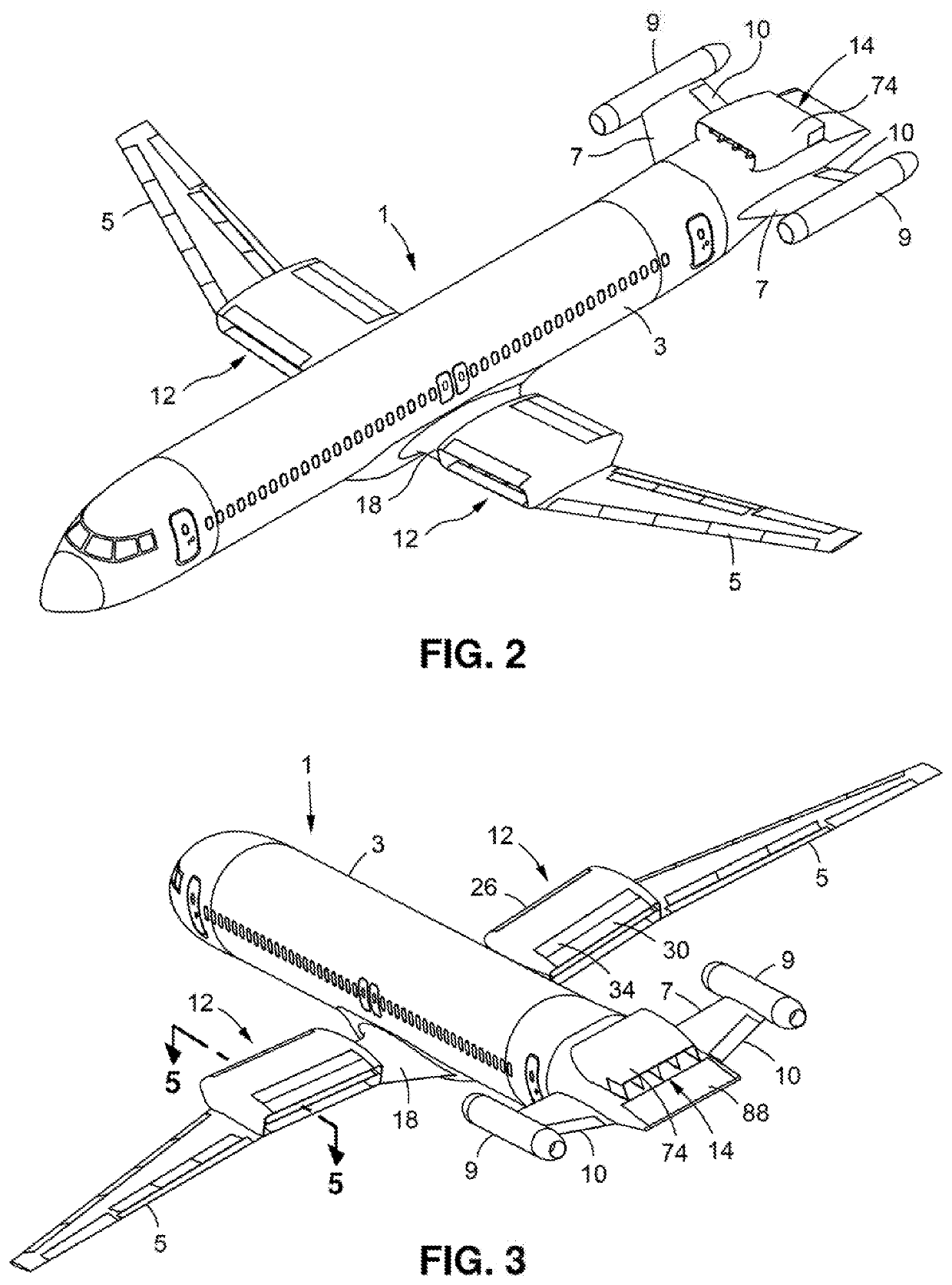
[0019]Referring initially to FIGS. 1-3 of the drawings, there is shown an aircraft 1 including a fuselage 3 hashing a round nose and a flat tapered tail, a pair of horizontal wings 5 extending outwardly and in opposite directions from the fuselage 3, a pair of horizontal tail sections 7 extending outwardly and in opposite directions from the tail of the fuselage 3, a pan of aft turbo generators 9 carried at the outside ends of respective ones of the tail sections 7, and elevator flaps 10 that are pivotally connected to the rear of respective ones of the tail sections 7. As an important improvement to the aircraft 1 of this invention relative to a conventional aircraft, the aircraft includes an airfoil-shaped, generally rectangular, and multi-function nacelle 12 that is mounted on the top of each wing 5 and a generally rectangular boundary layer nacelle 14 that is mounted on the top of the tail of the fuselage 3 between the turbo generators 9. As will be disclosed in greater detail h...


PUM


Abstract

An aircraft having a fuselage with a nose and a flat tail at opposite ends and a pair of wings extending therefrom. A pair of nacelles are detachably connected to the top of respective ones of the wings to be spaced from the fuselage to establish an air flow space therebetween, Each wing-mounted nacelle includes a plurality of fans, a corresponding plurality of electric motors to drive the fans, and dividers that separate the fans from one another. Each wing-mounted nacelle also includes a pair of rotatable air inlet slats at an air intake end and a pair of rotatable air exhaust flaps at an air exhaust end that are rotated relative to one another to control horizontal propulsive thrust, thrust vectoring and thrust reversing of the aircraft. A third nacelle is mounted on top of the flat tail of the fuselage between a pair of horizontal turbo generators.

Description

BACKGROUND OF THE INVENTIONField of the Invention[0001]This invention relates to a pair of airfoil-shaped, rectangular and multi-functional nacelles each of which having a plurality of horizontally extending electric motors and motor driven fans and being mounted on the top of and lying above respective ones of a pair of wings of an aircraft. The nacelles have rotatable air flow control surfaces at opposite air intake and, exhaust ends thereof to provide the aircraft with enhanced horizontal propulsive thrust, thrust vectoring and thrust reversing.Background Art[0002]Aircraft propulsion systems currently consist of large round nacelles carried underneath the aircraft wing. As engines and nacelles grow larger in diameter, they require moving the wing upward or increasing the length of the landing gear to provide increased ground clearance. The larger nacelles have more surface area which produces more drag. The round nacelle also takes up space along the lateral wing surface that inh...

Claims


Application Information

Patent Timeline
Patent Type & Authority Applications(United States)
IPC IPC(8): B64C15/00B64D27/26B64D29/02B64D33/02B64D33/04B64D27/12B64D27/14B64C7/02
CPCB64D29/02B64D27/14B64C15/00B64D27/26B64D33/04B64C7/02B64D27/12B64D33/02B64C15/02B64D27/24Y02T50/60B64D2027/026B64D27/16B64C5/02B64D27/02Y02T50/10B64C21/01
Inventor CUMMINGS, DAROLD B.
Owner WRIGHT ELECTRIC INC
Why Eureka
Try Eureka