A method for monitoring a common-rail injector for large diesel and dual-fuel engines and injector configured to implement this method

Inactive Publication Date: 2020-10-29
OMT DIGITAL SRL
View PDF0 Cites 0 Cited by
  • Summary
  • Abstract
  • Description
  • Claims
  • Application Information

AI Technical Summary

Benefits of technology

The patent claims are part of the information provided about the invention. They explain the technical effects of the invention in a simple way.

Problems solved by technology

An aging or anomaly of the injector that leads to creating a different injection diagram from that of the design involves a degradation of performances and an increase in consumption and / or emissions.
Having to dose very small quantities of fuel, degradation over time of the relationship between the duration of the command and the quantity of fuel injected is inevitable.
Measuring the position of the injector needle is very complex as the injector needle is completely immersed in the fuel at very high pressures.
This makes it very complicated to place a sensor in the immediate vicinity of the injector needle.
This in fact entails considerable difficulties in providing for the passage of the sensor connection cables from a very high pressure environment, guaranteeing tightness.
This technique only detects the extreme positions of the path of the injector needle, but does not provide information on the intermediate sections of the path.
One of the problems of this solution is that the sensor must be placed beyond the metal wall that contains the injector needle and the fuel under pressure.
This means that most of the magnetic field is shielded by the casing, making it difficult to obtain high signal-to-noise ratios.
It is also difficult to arrange a sensor within thin walls arranged in the vicinity of the combustion chamber and subject to high temperatures.
In addition, the injector pulverizer (consisting of the part including the injector needle and the nozzle) needs periodic replacements as it is subject to wear.
The presence of a sensor in this part of the injector creates problems of electrical connection and the increase in the cost of spare parts.
This technique is effective for evaluating the operation of the injection stage but provides limited information on the operation of the control valve since the perturbations it generates during switching are not detected on the supply line due to the presence of calibrated orifices between the control valve and the power line.
Therefore, with this technique it is not possible to use a single sensor to monitor the operation of the entire injector.
Furthermore, in gas mode operation, the small quantity of fuel injected requires extremely reduced flow rates and therefore a very low signal / noise ratio, which does not allow an accurate diagnosis in such operating conditions.
One of the problems with detecting the pressure in the control chamber is that the control chamber has very small dimensions, so that it is not easy to insert a pressure sensor in this area.
i) the instantaneous pressure of the fluid inside the channel is not exactly equal to the instantaneous pressure in the control chamber because the channel-chamber system constitutes a hydraulic resonator that creates pressure oscillations, and the distortion due to the interference of pressure waves can disturb the signal, making analysis more difficult;
v) in the operation diagnostics of an injector for large naval engines, it is of particular importance detecting the instant in which the needle reaches, or leaves, the surface of the head plate that delimits the control chamber at the top, and creates the mechanical stop of the needle in its opening stroke; the known measurement methods are based on the analysis of the pressure signal in the channel to deduce the instants of stopping and detachment of the needle from its upper stop; this can lead to inaccurate results given that these events cannot always be easily defined at the algorithm level given the limited amplitude on the pressure signal of the perturbation induced by the needle when it enters the stop or leaves the upper stop surface.

Method used


Image

  • A method for monitoring a common-rail injector for large diesel and dual-fuel engines and injector configured to implement this method
  • A method for monitoring a common-rail injector for large diesel and dual-fuel engines and injector configured to implement this method
  • A method for monitoring a common-rail injector for large diesel and dual-fuel engines and injector configured to implement this method

Examples


Embodiment Construction

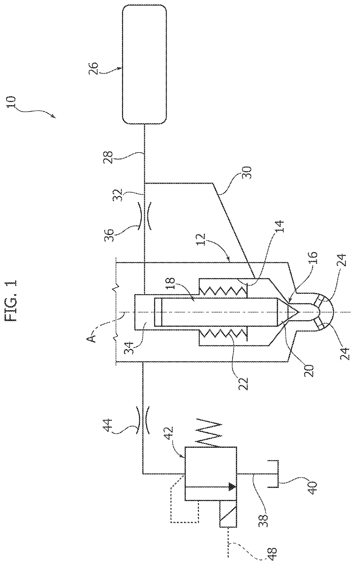
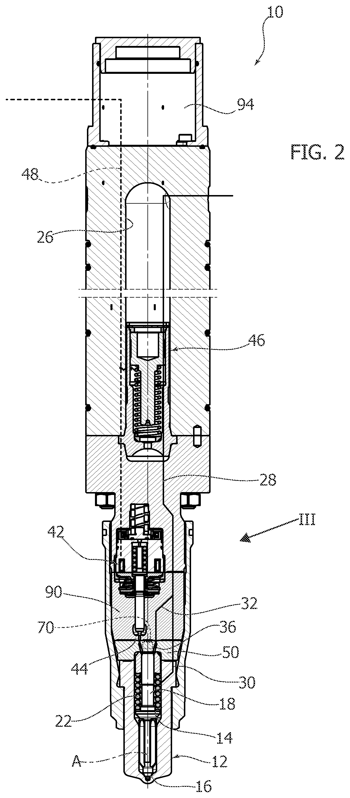
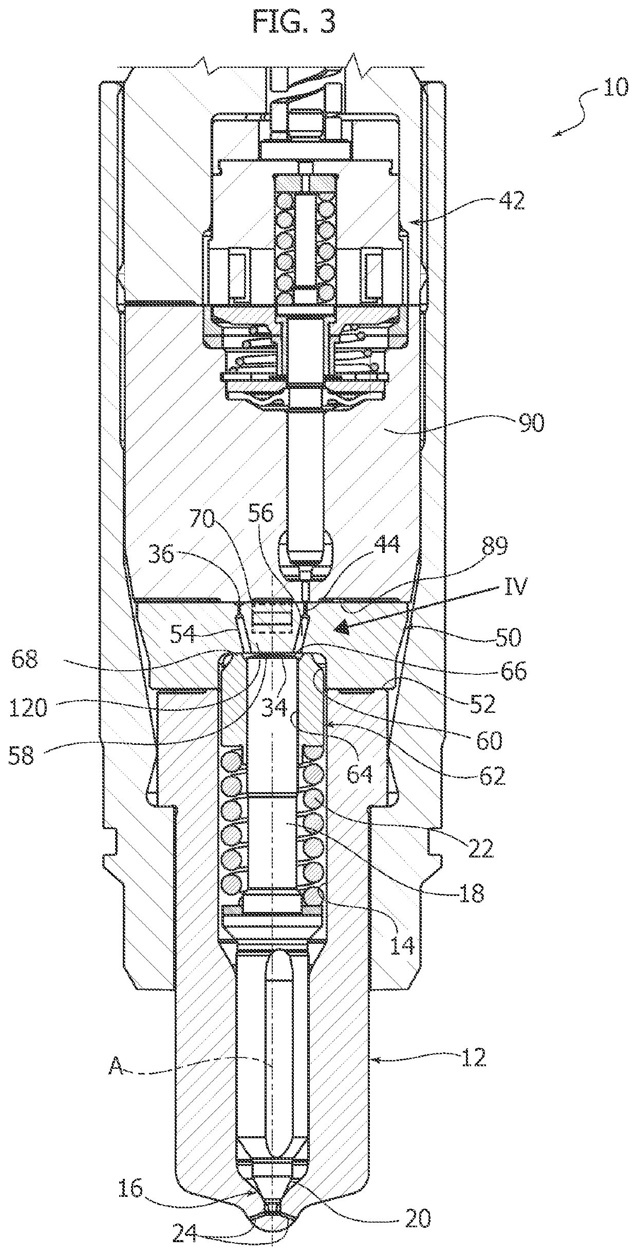
[0041]In FIG. 1, an injector for a common-rail injection system is indicated by 10. The injector 10 comprises a pulverizer 12 having a fuel delivery chamber 14 having a valve seat 16. An injector needle 18 extends into the delivery chamber 14 and has a sealing surface 20 that cooperates with the valve seat 16. The injector needle 18 is movable along its longitudinal axis A between a closed position in which the sealing surface 20 abuts against the valve seat 16, and an open position in which the sealing surface 20 is spaced apart from the valve seat 16. A spring 22 tends to push the injector needle 18 towards the closed position. The pulverizer 12 has a plurality of injection holes 24 through which the pressurized fuel located in the delivery chamber 14 is pulverized when the injector needle 18 is in the open position.

[0042]The injector 10 comprises a storage volume 26 which, together with similar storage volumes of other injectors of the same engine, constitutes a distributed commo...


PUM


Abstract

A method for monitoring an injector for common-rail injection systems includes detecting an electrical signal indicative of a deformation of a diaphragm of a head plate having a reaction surface facing a control chamber of the injector and processing the deformation signal to determine characteristic data of the operation of the injector.

Description

FIELD OF THE INVENTION[0001]The present invention refers, in general, to injection systems for large diesel and dual-fuel engines, for example, for large naval engines.[0002]More specifically, the invention relates to a method for monitoring an injector for common-rail injection systems for large diesel and dual-fuel engines.[0003]According to another aspect, the present invention also relates to an injector for common-rail injection systems.DESCRIPTION OF THE PRIOR ART[0004]A common-rail injection system comprises a pump that pressurizes the fuel in a high-pressure (common-rail) accumulator that feeds the injectors. The injectors are provided with a valve seat and an injector needle movable between a closed position and an open position. The position of the injector needle is determined by the intensity of two hydraulic forces generated by the action of pressurized fluid on appropriate surfaces of influence.[0005]The pressurized fluid is fed into a delivery chamber located upstream...

Claims


Application Information

Patent Timeline
IPC IPC(8): F02M63/02F02M47/02
CPCF02M2200/21F02M63/0026F02M2200/28F02M63/0225F02M2200/244F02M47/027F02M2200/703F02D2200/0602F02M55/025F02M61/16F02M57/005F02D41/22F02M2200/247F02D2041/224F02M65/003F02M65/001F02M65/005G01L23/10Y02T10/40F02D41/2467F02D41/3827F02M51/061F02D41/401G01L1/16F02M2200/16
Inventor COPPO, MARCO
Owner OMT DIGITAL SRL
Why Eureka
Try Eureka