
Outdoor unit, air conditioner, fan guard, and method of manufacturing fan guard

a technology of outdoor units and fan guards, which is applied in the field of outdoor units, air conditioners, fan guards, and methods of manufacturing fan guards, can solve the problems of mechanical strength not being secured and the blowing efficiency being reduced, and achieve the effect of reducing the blowing resistan

Active Publication Date: 2020-11-05
SAMSUNG ELECTRONICS CO LTD
View PDF2 Cites 2 Cited by
  • Summary
  • Abstract
  • Description
  • Claims
  • Application Information

AI Technical Summary

Benefits of technology

This patent describes an outdoor unit that improves mechanical strength and reduces blowing resistance. The design of the unit reduces the free ends of ribs and minimizes the width of radial ribs to increase surface contact between opposing piece parts. This results in a stronger fan guard with less resistance during blowing.

Problems solved by technology

A large upward type outdoor unit may be installed on a roof of a building, for example, and because of a large air flow rate of the large upward type outdoor unit, especially when the radial ribs that hinder swirling flow of the blowing fan are thick, the radial ribs act as a blowing resistance, resulting in a decrease in blowing efficiency.
When the free ends are in surface contact with each other in a misaligned state, a portion (area) where the wind blown from the blowing fan touches becomes large, and the portion becomes a noise source to generate noise.
When viewed from the cross section orthogonal to the stretching direction of the respective ribs, the mechanical strength may not be secured when the widths of the respective ribs are too small, and the respective ribs may not be bent when the widths of the respective ribs are too large.

Method used


Image

  • Outdoor unit, air conditioner, fan guard, and method of manufacturing fan guard
  • Outdoor unit, air conditioner, fan guard, and method of manufacturing fan guard
  • Outdoor unit, air conditioner, fan guard, and method of manufacturing fan guard

Examples


Embodiment Construction

[0040]Hereinafter, an embodiment of an outdoor unit according to the present invention will be described with reference to the drawings.

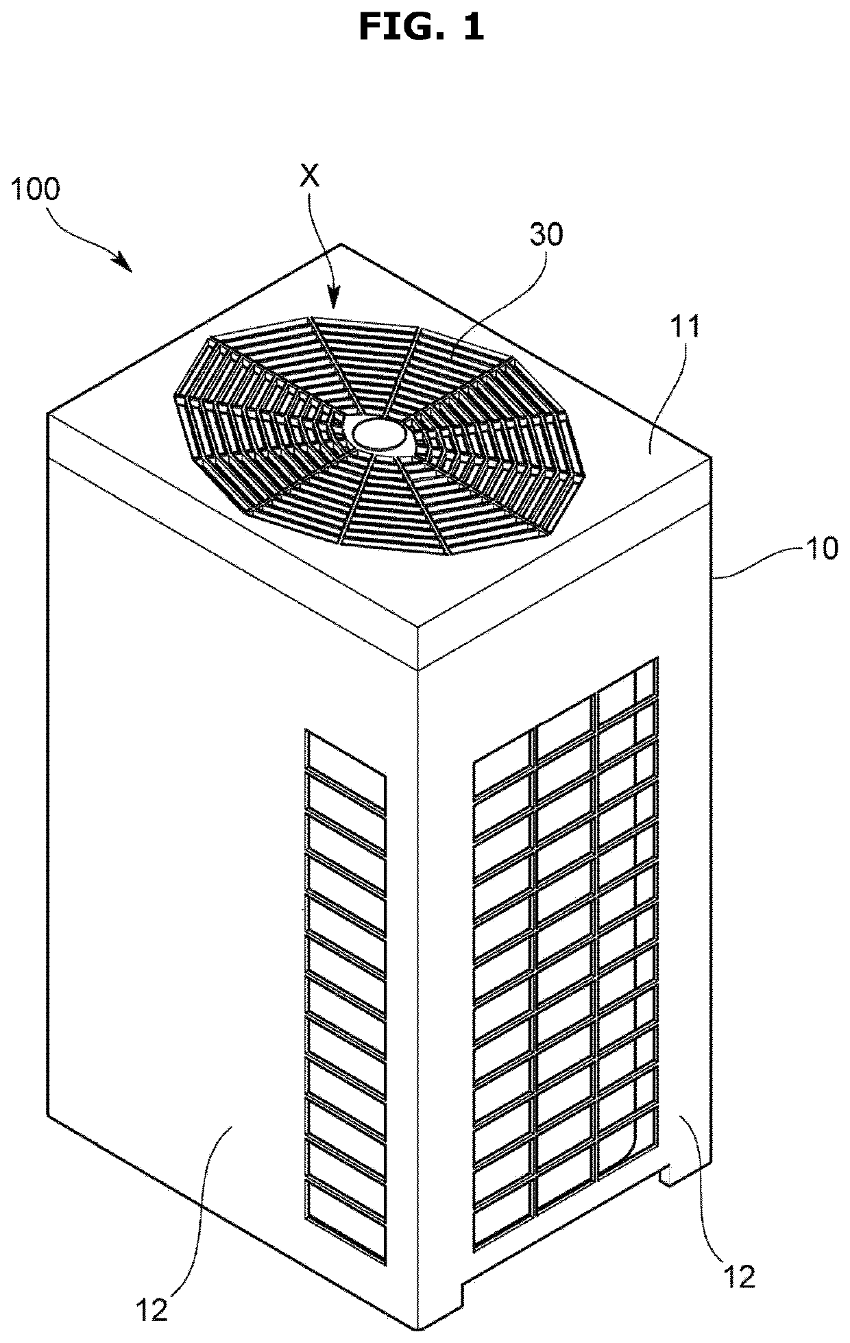
[0041]An outdoor unit 100 according to the present embodiment is connected to an indoor unit having at least an indoor heat exchanger by piping to constitute an air conditioner, and is, for example, an upward type outdoor unit installed on a roof of a building.

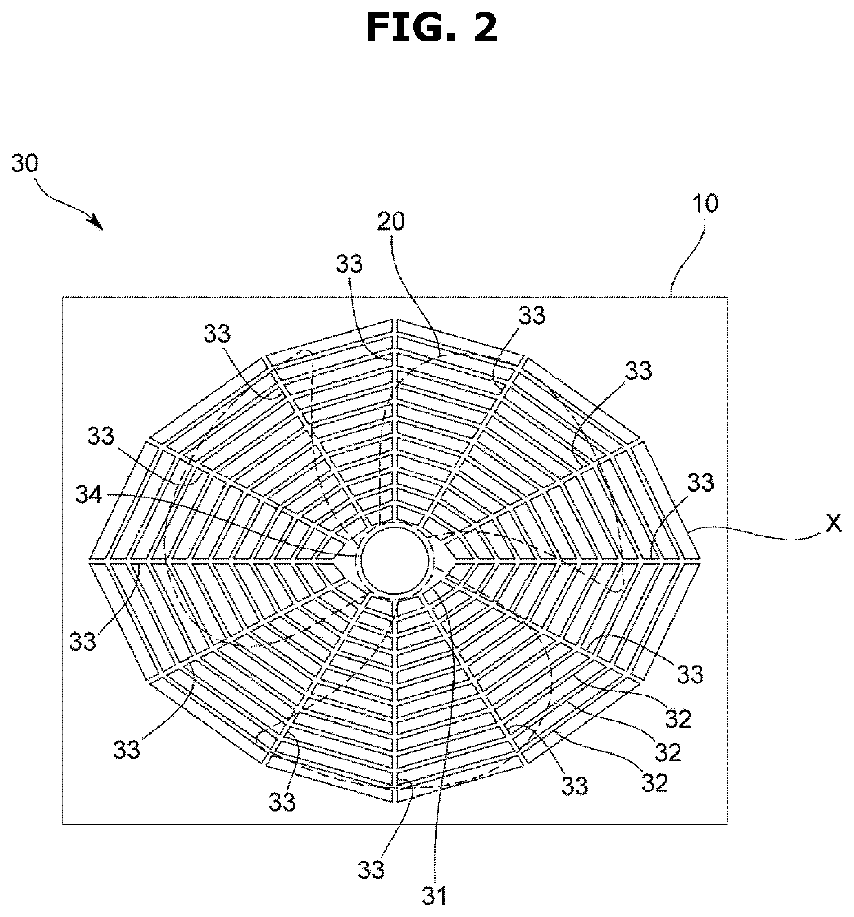
[0042]Specifically, as shown in FIGS. 1 and 2, the outdoor unit 100 includes a housing 10 in which an air discharge port X is formed on an upper wall 11, a blowing fan 20 disposed inside the housing 10 to correspond to the air discharge port X, and a fan guard 30 configured to cover the blowing fan 20.

[0043]The housing 10 is formed in, for example, a substantially rectangular parallelepiped shape to accommodate an outdoor heat exchanger, which is not shown, and air suction ports are formed on side walls 12. The housing 10 according to the present embodiment has one of the air discharge port X ...


PUM


Abstract

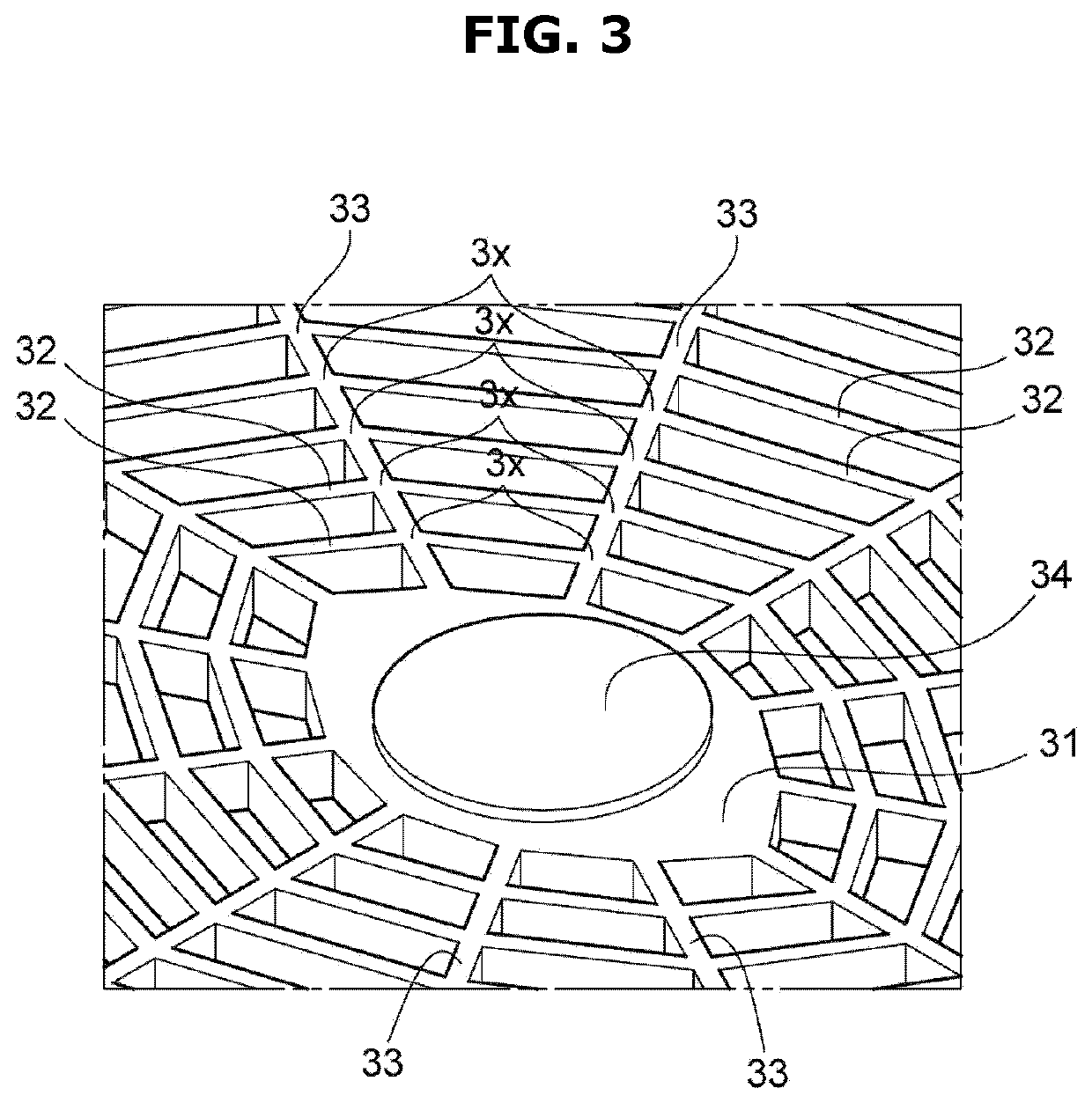
The present disclosure is to reduce a blowing resistance while securing a mechanical strength of a fan guard.An outdoor unit 100 includes a housing 10 in which an air discharge port X is formed on an upper wall 11, a blowing fan 20 disposed inside the housing 10 to correspond to the air discharge port X, and a fan guard 30 configured to cover the blowing fan 20, wherein the fan guard 30 includes a plurality of annular ribs 32 disposed to be spaced apart from each other in a radial direction of the blowing fan 20, and radial ribs 33 configured to connect a plurality of the annular ribs 32, and wherein the radial ribs 33 are formed such that free ends 3a thereof are bent in the same direction in a cross section orthogonal to a stretching direction and a pair of opposing piece portions 3b including each of the free ends 3a are in surface contact with each other.

Description

CROSS-REFERENCE TO RELATED APPLICATIONS[0001]This application is a 371 of International Application No. PCT / JP2018 / 045819 filed on Dec. 13, 2018, which claims priority to Japanese Patent Application No. 2017-243669 filed on Dec. 20, 2017, the disclosures of which are herein incorporated by reference in their entirety.BACKGROUND1. Field[0002]The present disclosure relates to an upward type outdoor unit, an air conditioner including the outdoor unit, a fan guard commonly used in the outdoor unit, and a method of manufacturing the fan guard.2. Description of Related Art[0003]An upward type outdoor unit includes a housing having an air discharge port on an upper wall, a blowing fan installed inside the housing to correspond to the air discharge port, and a fan guard covering the blowing fan, as shown in Patent Document 1.[0004]The fan guard includes a plurality of annular ribs spaced apart from each other in a radial direction of the blowing fan, and radial ribs connecting the annular r...

Claims


Application Information

Patent Timeline
IPC IPC(8): F24F1/56F24F1/50F24F13/20
CPCF24F1/56F24F13/20F24F1/50F24F1/38F24F1/40F24F1/48
Inventor TAKAHARA, TAKESHIISHIKAWA, HIDEKINAKAGAWA, SUGURUCHOI, JEIMINYOO, JAESUNGYOON, JOONHOJIN, DONGSIK
Owner SAMSUNG ELECTRONICS CO LTD
Learn More