Input device

Active Publication Date: 2020-11-05
ALPS ALPINE CO LTD
View PDF0 Cites 0 Cited by
  • Summary
  • Abstract
  • Description
  • Claims
  • Application Information

AI Technical Summary

Benefits of technology

[0014]In the above input device, the end adhesive region in the adhesive layer may have an adhesiveness decrescent region in which the distance between the film sensor and the convex surface is increased and adhesiveness is reduced. Thus, adhesiveness by the adhesive layer is gradually reduced toward the extending portion of the main body, suppressing an abrupt change in adhesive force.
[0015]In the above input device, the adhesiveness decrescent region may be provided so that the distance between the film sensor and the convex surface is increased and the amount of adhesive forming the adhesive layer is lessened. Thus, adhesiveness by the adhesive layer is gradually reduced toward the extending portion of the main body, suppressing an abrupt change in adhesive force.
[0016]In the above input device, the adhesiveness decrescent region may be provided so that the distance between the film sensor and the convex surface is increased and the area of the adhesive layer in contact with both of the film sensor and the convex surface

Problems solved by technology

If a position at which this bending stress concentrates is on an electrode of the sensor o

Method used


Image

  • Input device
  • Input device
  • Input device

Examples


Embodiment Construction

[0027]An embodiment of the present invention will be described below with reference to the drawings. In the descriptions below, like elements will be denoted by like reference characters and repeated descriptions will be appropriately omitted for members that have been described once.

The Structure of Input Device

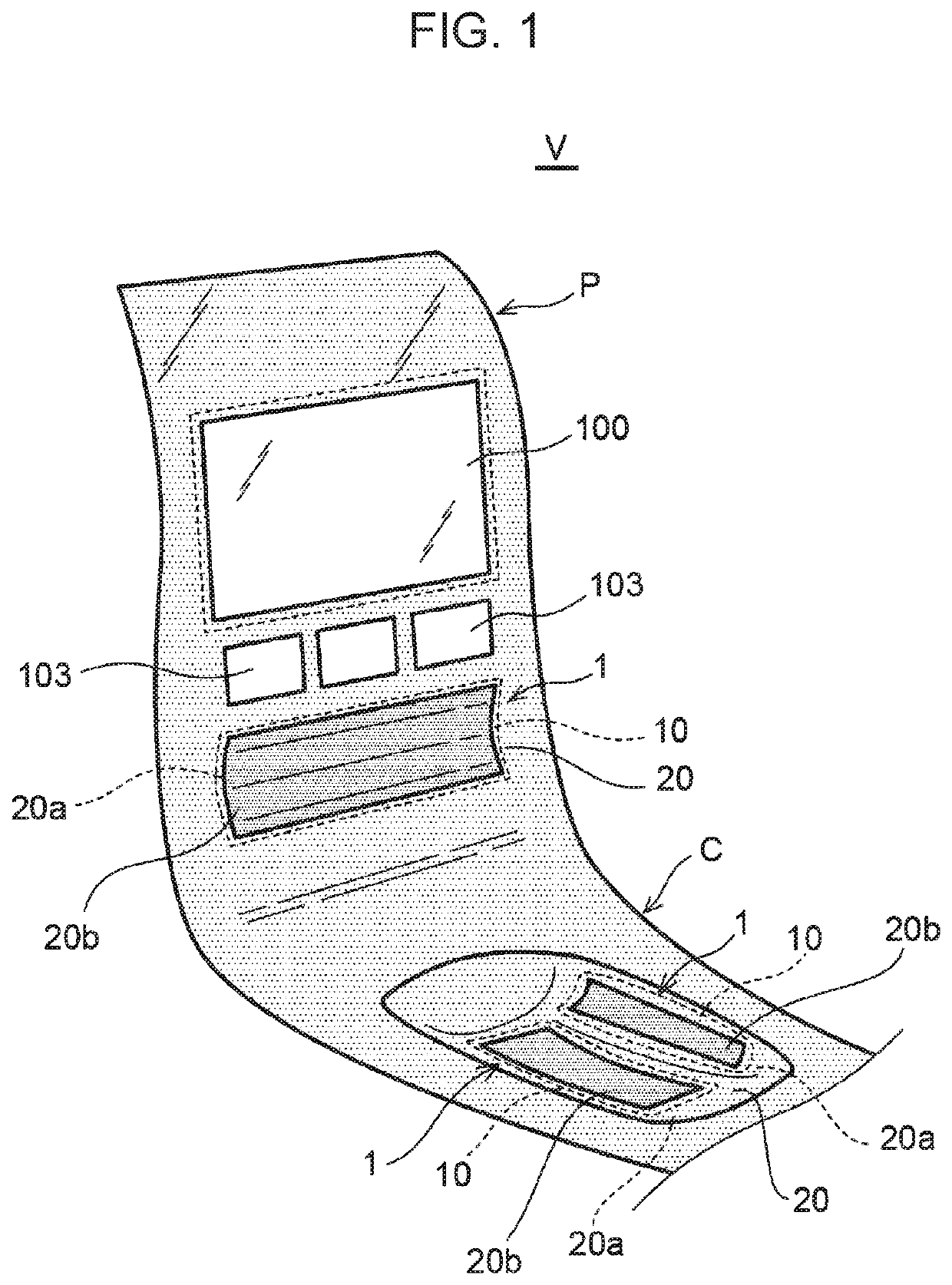
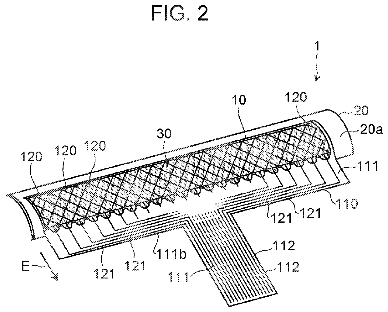
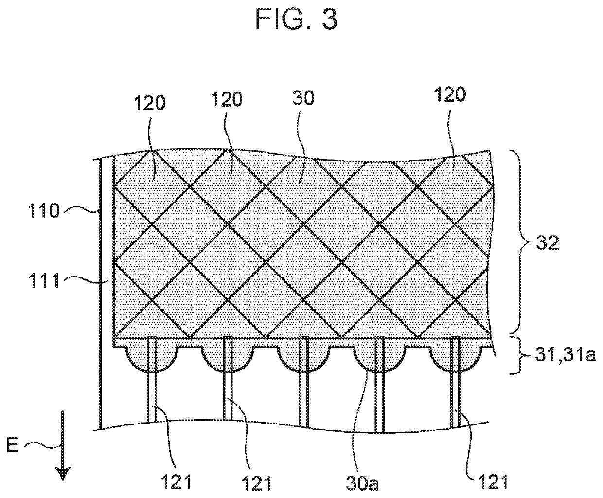
[0028]FIG. 1 is a schematic diagram illustrating an application example of an input device according to this embodiment. FIG. 2 is a perspective view illustrating the input device according to this embodiment. FIG. 3 is a schematic plan view in which electrode portions and an adhesive layer are partially enlarged. FIGS. 4A and 4B are schematic cross-sectional views of the input device according to this embodiment; FIG. 4A is a cross-sectional view when viewed in the length direction and FIG. 4B is a partially enlarged view of a connection region.

[0029]An input device 1 according to this embodiment is a touch-type detection apparatus that detects a position at which a finger ...


PUM

PropertyMeasurementUnit
Adhesivityaaaaaaaaaa
Areaaaaaaaaaaa
Distanceaaaaaaaaaa

Abstract

An input device has a film sensor and a cover member having a convex surface. The film sensor includes: a support substrate that has a film-like main body and an extending portion extending from an end of the main body toward the outside; a plurality of electrode portions provided on a surface of the main body; and lead patterns that extend from the main body to the extending portion and are electrically continuous to the plurality of electrodes. A surface of the main body, the surface being on the same side as the plurality of electrode portions, is attached to the convex surface through an adhesive layer. An end adhesive area, in the adhesive layer, positioned on the same side as the extending portion, has lower adhesiveness than a central adhesive area, in the adhesive layer, positioned on the same side as the central portion of the convex surface.

Description

CLAIM OF PRIORITY[0001]This application is a Continuation of International Application No. PCT / JP2018 / 048208 filed on Dec. 27, 2018, which claims benefit of Japanese Patent Application No. 2018-011570 filed on Jan. 26, 2018. The entire contents of each application noted above are hereby incorporated by reference.BACKGROUND OF THE INVENTION1. Field of the Invention[0002]The present invention relates to an input device, and more particularly to an input device having a film sensor that detects a position that a finger or the like has approached.2. Description of the Related Art[0003]A film sensor widely used in an input device has a sensor that detects a position at which a finger or the like has approached a detection region (in the description below, “approach” includes “touch”). In a film sensor in a mutual capacitance method, for example, an electrode on a driving side and an electrode on an output side are provided. A drive pulse is given to the electrode on the driving side, and...

Claims


Application Information

Patent Timeline
IPC IPC(8): G06F3/044B32B7/12
CPCG06F2203/04102B32B7/12G06F2203/04103G06F3/0446B32B2457/208G06F3/044G06F3/041C09D5/00
Inventor SASAGAWA, HIDETOASAKAWA, TAKASHI
Owner ALPS ALPINE CO LTD
Why Eureka
Try Eureka