

Stent graft transport device
- Summary
- Abstract
- Description
- Claims
- Application Information
AI Technical Summary
Benefits of technology
Problems solved by technology
Method used
Image

Examples
Embodiment Construction
[0067]One embodiment of this invention will be explained with reference to drawings.
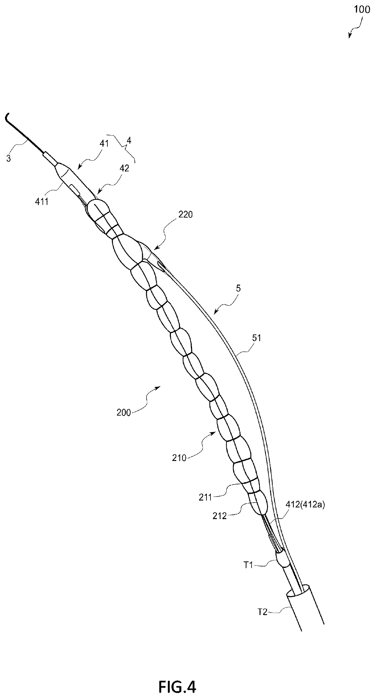
[0068]A stent graft transport device 100 in accordance with this embodiment is to transport an artificial blood vessel (a stent graft 200 in this embodiment) to a lesion part through a blood vessel and indwell the artificial blood vessel.
[0069]Before explaining the stent graft transport device 100, the stent graft 200 as being an object to be transported will be briefly explained.
[0070]200>
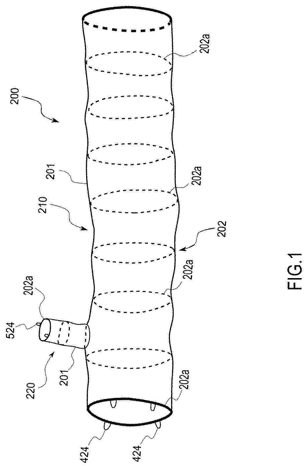
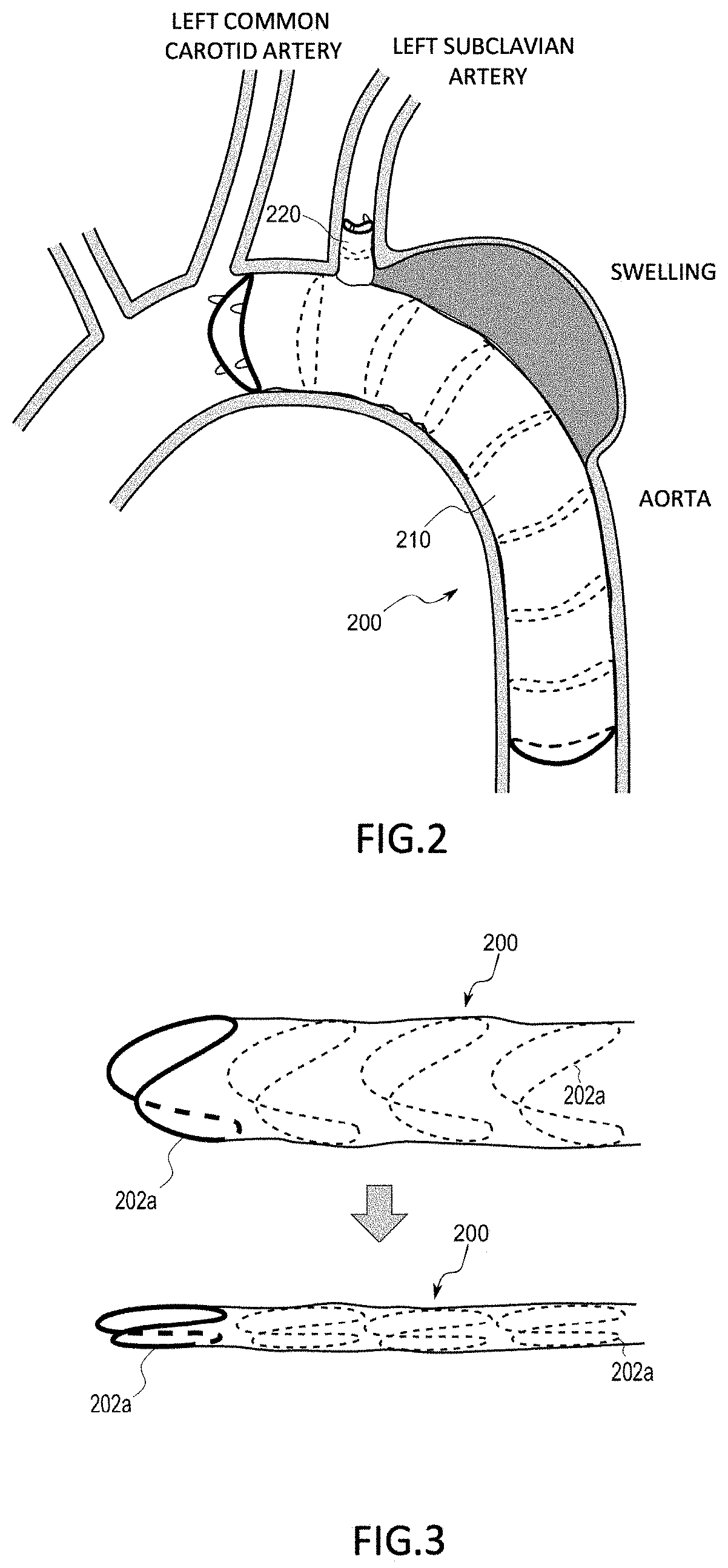
[0071]The stent graft 200 in accordance with this embodiment is, as shown in FIG. 1 and FIG. 2, a branched shape comprising a long and large diameter main tube 210 and a short and small diameter branch tube 220 that bifurcates from a part of the main tube 210, and is indwelled in, for example, the arch aorta in this embodiment.
[0072]The main tube 210 is so arranged that a distal end (an upstream end) thereof is positioned between the left subclavian artery and the left common carotid artery and extends downstream w...
PUM
 Abstract
Description
Claims
Application Information