
Waterway switching mechanism and method for switching the waterway switching mechanism

a technology of waterway switching and waterway, applied in water installations, spray nozzles, constructions, etc., can solve the problems of increased production cost and rejection rate, inconvenient switching, etc., and achieve the effect of improving switching stability and easy assembly of the structur

Active Publication Date: 2020-11-12
XIAMEN SOLEX HIGH TECH IND CO LTD
View PDF0 Cites 8 Cited by
  • Summary
  • Abstract
  • Description
  • Claims
  • Application Information

AI Technical Summary

Benefits of technology

The technical solution of the present patent text has advantages over existing techniques. It uses a water dividing plate that only rotates, reducing cost and space. The push rod and movable block have guiding surfaces that enable smooth movement. The movable block and water dividing plate rotate together, making the switch easy. The mounting and structure are simple. A central shaft is used for easy assembly and improved switching stability. Overall, the invention has a compact and cost-effective structure with improved stability and ease of use.

Problems solved by technology

The structure is complicated, the occupied space is large, and the switching resistance is large, resulting in inconvenient switching.
Since the water dividing plate has to be raised, a water dividing body and a gasket must adopt a secondary filling process, resulting in increases in production cost and in rejection rate due to defects.

Method used


Image

  • Waterway switching mechanism and method for switching the waterway switching mechanism
  • Waterway switching mechanism and method for switching the waterway switching mechanism
  • Waterway switching mechanism and method for switching the waterway switching mechanism

Examples


embodiment 1

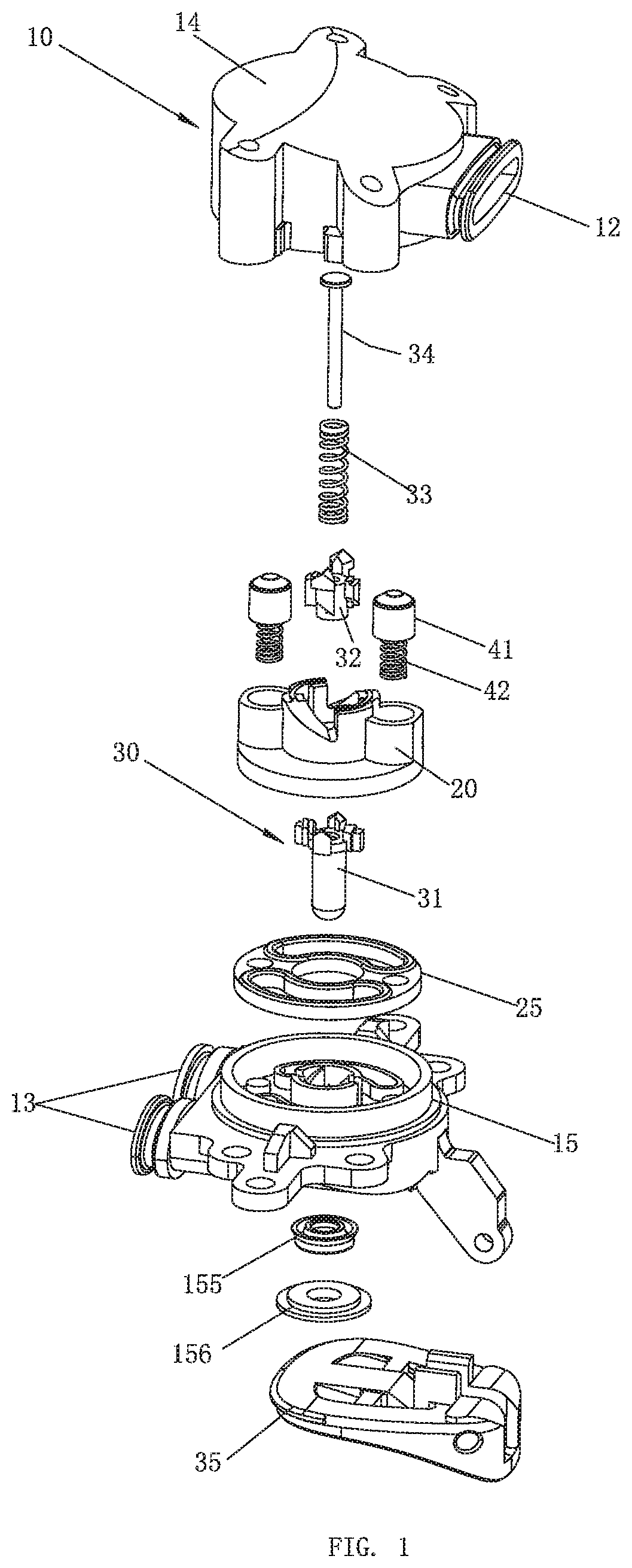
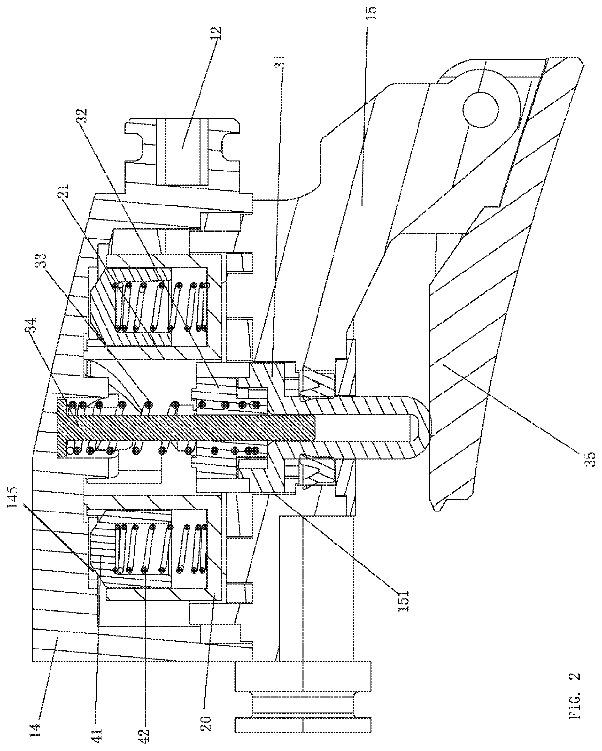
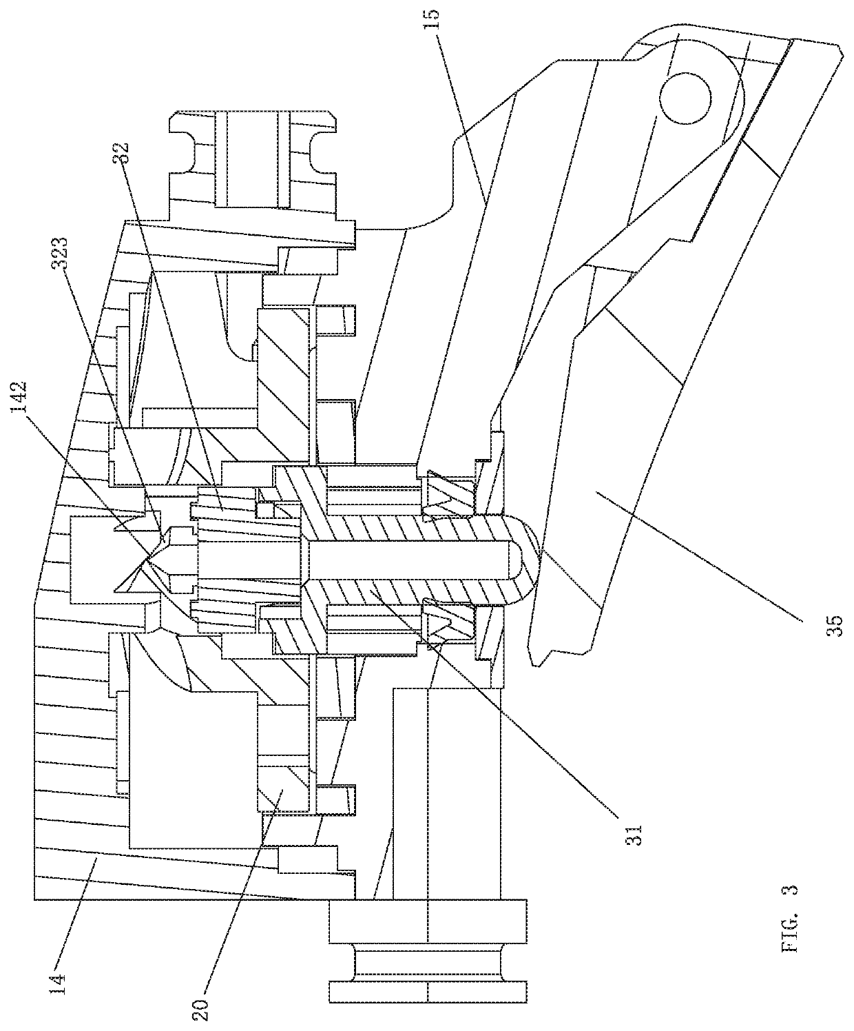
[0073]Referring to FIGS. 1-11, a waterway switching mechanism comprises a mounting portion 10, a water dividing plate 20, and a driving mechanism 30. The driving mechanism 30 comprises a push rod 31, a movable block 32, an elastic body 33, a central shaft 34, and a button 35.

[0074]The mounting portion 10 comprises a water dividing chamber 11, a water inlet passage 12 configured to supply water to the water dividing chamber 11, and a plurality of water dividing passages 13. The water inlet passage 12 is connected to the water dividing chamber 11. In the example embodiment, the plurality of water dividing passages 13 comprises two water dividing passages 13, but the number of water dividing passages is not limited thereto. The plurality of water dividing passages 13 can comprise three, four, or more than four water dividing passages 13 when needed. The water dividing plate 20 is rotatably disposed in the water dividing chamber 11 of the mounting portion 10 and cooperates with the two ...

embodiment 2

[0089]Referring to FIGS. 16-19, this embodiment differs from Embodiment 1 in that the structure configured to restrict the rotation of the movable block 32 in the second direction is different from that of Embodiment 1. In this embodiment, the first outer convex portion 314 comprises an extending portion extending above the push rod 31, and the protruding portion of the first outer convex portion 314 defines the angle facing inward. A rotation limiting member 316 is fixedly disposed at an intersection of the first upper guiding surface 311 and the second upper guiding surface 312. A periphery of a bottom of the body 324 of the movable block 32 comprises an arc-shaped opening 327 extending inward. The number of arc-shaped openings 327 is the same as the number of first outer convex portions 314 (the number of rotation limiting members 316 is the same as the number of arc-shaped openings 327), and the rotation limiting member 316 is connected to the arc-shape opening 327 to prevent th...

embodiment 3

[0090]Referring to FIGS. 20-30, this embodiment differs from Embodiment 1 in that, in Embodiment 3, the water inlet passage 12 is considered to be a first water dividing passage and a plurality of other water dividing passages 13 are controlled to be switched to be connected with the water inlet passage 12. That is, the plurality of water dividing passages 13 are controlled to be open and to be closed. In this embodiment, a water passage is controlled to be closed or to be open. In some embodiments, with reference to FIGS. 20-30, a handheld shower comprises a waterway switching mechanism. The waterway switching mechanism comprises a driving mechanism 30, a mounting portion 10, a driven plate 20′, a water dividing plate 20, and a ratchet wheel-ratchet intermittent movement mechanism 50. In this embodiment, for example, the driven plate 20′ is driven to rotate to control the water passage to be closed and to be open. The driving mechanism 30 of Embodiment 1 is substantially the same a...


PUM


Abstract

The present disclosure discloses a waterway switching mechanism comprising a mounting portion, a water dividing plate, and a driving mechanism. The mounting portion comprises at least one water dividing passage, and the water dividing plate cooperates with the at least one water dividing passage to switch a waterway through rotation of the water dividing plate. A third upper guiding surface of the movable block contacts and couples to a first inner guiding surface of the water dividing plate to enable the movable block to move to drive the water dividing plate to rotate in a first direction. The movable block cooperates with a fixing guiding surface of an upper matching portion of the mounting portion to enable the push rod to move to drive the movable block and the water dividing plate to rotate in the first direction.

Description

RELATED APPLICATIONS[0001]This application claims priority to Chinese Patent Application 201910379860.3, filed on May 8, 2019, and Chinese Patent Application 201911167484.8, filed on Nov. 25, 2019. Chinese Patent Application 201910379860.3 and Chinese Patent Application 201911167484.8 are incorporated herein by reference.FIELD OF THE DISCLOSURE[0002]The present disclosure relates to the field of sanitary ware, and in particular to a waterway switching mechanism and a switching method thereof.BACKGROUND OF THE DISCLOSURE[0003]There are many ways to switch waterways in sanitary ware. The common two methods are the sliding switching method and the rotating switching method. The sliding switching method refers to controlling the water outflow of different waterways by relative sliding. The rotating switching method refers to controlling the water outflow of different waterways by relative rotation. The structure of a waterway switching mechanism used for the rotating switching method co...

Claims


Application Information

Patent Timeline
Patent Type & Authority Applications(United States)
IPC IPC(8): B05B1/18B05B1/30E03C1/04B05B1/16
CPCB05B1/1681E03C1/0404B05B1/1654B05B1/3086B05B1/18B05B1/1636B05B1/1663B05B12/002B05B1/169
Inventor LIN, FENGDECHEN, WENXINGCHEN, DONGHAICAO, BIN
Owner XIAMEN SOLEX HIGH TECH IND CO LTD
Learn More