Eureka AIR delivers breakthrough ideas for toughest innovation challenges, trusted by R&D personnel around the world.

Cellular communication systems having antenna arrays therein with enhanced half power beam width (HPBW) control

Active Publication Date: 2020-11-12
COMMSCOPE TECH LLC
View PDF0 Cites 1 Cited by
  • Summary
  • Abstract
  • Description
  • Claims
  • Application Information

AI Technical Summary

Benefits of technology

The invention relates to antenna arrays that can be used in wireless communication systems. The arrays have multiple columns of radiating elements that are responsive to different RF feed signals. A power divider circuit is used to drive the columns with energy from the RF feed signals. The circuit ensures that the energy is efficiently distributed to the columns. The antenna arrays can be used in systems that require high data rates and can improve signal quality. The technical effect of the invention is to improve the performance of wireless communication systems by improving the distribution of energy to the radiating elements.

Problems solved by technology

However, due to local zoning ordinances and / or weight and wind loading constraints for the antenna towers, etc. there is often a limit as to the number of base station antennas that can be deployed at a given base station.
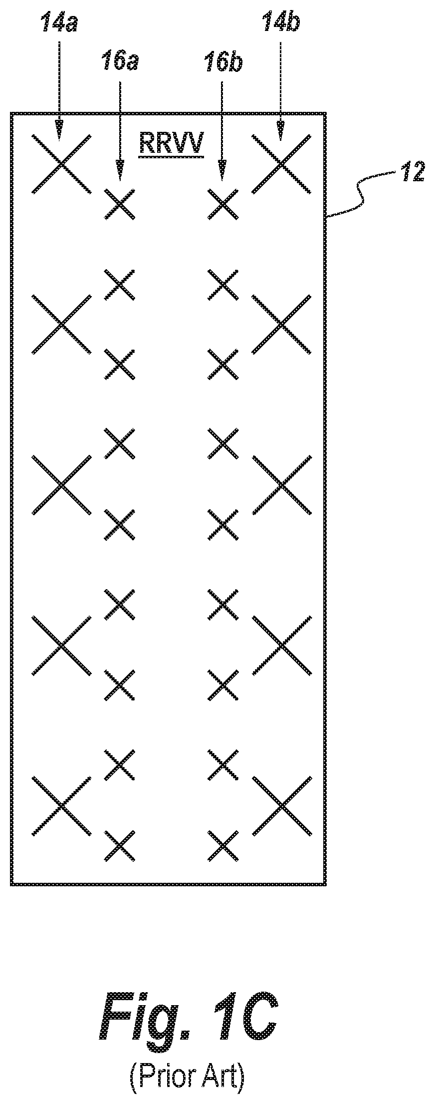
RRVV antennas, however, are challenging to implement in a commercially acceptable manner because achieving a 65° azimuth HPBW antenna beam in the low-band typically requires low-band radiating elements that are at least 200 mm wide.
Such large RRVV antennas may have very high wind loading, may be very heavy, and / or may be expensive to manufacture.
Unfortunately, as the linear arrays of radiating elements are aligned closer together, the degree of signal coupling between the linear arrays can increase significantly and this “parasitic” coupling can lead to an undesired increase in HPBW.
Similarly, any reduction in the dimensions of the low-band radiating elements will often cause an increase in HPBW.

Method used


Image

  • Cellular communication systems having antenna arrays therein with enhanced half power beam width (HPBW) control
  • Cellular communication systems having antenna arrays therein with enhanced half power beam width (HPBW) control
  • Cellular communication systems having antenna arrays therein with enhanced half power beam width (HPBW) control

Examples


Embodiment Construction

[0037]The present invention now will be described more fully with reference to the accompanying drawings, in which preferred embodiments of the invention are shown. This invention may, however, be embodied in many different forms and should not be construed as being limited to the embodiments set forth herein; rather, these embodiments are provided so that this disclosure will be thorough and complete, and will fully convey the scope of the invention to those skilled in the art. Like reference numerals refer to like elements throughout.

[0038]It will be understood that, although the terms first, second, third, etc. may be used herein to describe various elements, components, regions, layers and / or sections, these elements, components, regions, layers and / or sections should not be limited by these terms. These terms are only used to distinguish one element, component, region, layer or section from another region, layer or section. Thus, a first element, component, region, layer or sec...


PUM


Abstract

Antenna arrays include a first plurality of radiating elements in a first column thereof, which are responsive to a first plurality of RF feed signals derived from a first radio, and a second plurality of radiating elements in a second column thereof, which are responsive to a second plurality of RF feed signals derived from a second radio. A power divider circuit is provided, which is configured to drive a first one of the radiating elements at a first end of the second column of radiating elements with a majority of the energy associated with a first one of the first plurality of RF feed signals, and drive a first one of the radiating elements at a first end of the first column of radiating elements with a non-zero minority of the energy associated with the first one of the first plurality of RF feed signals.

Description

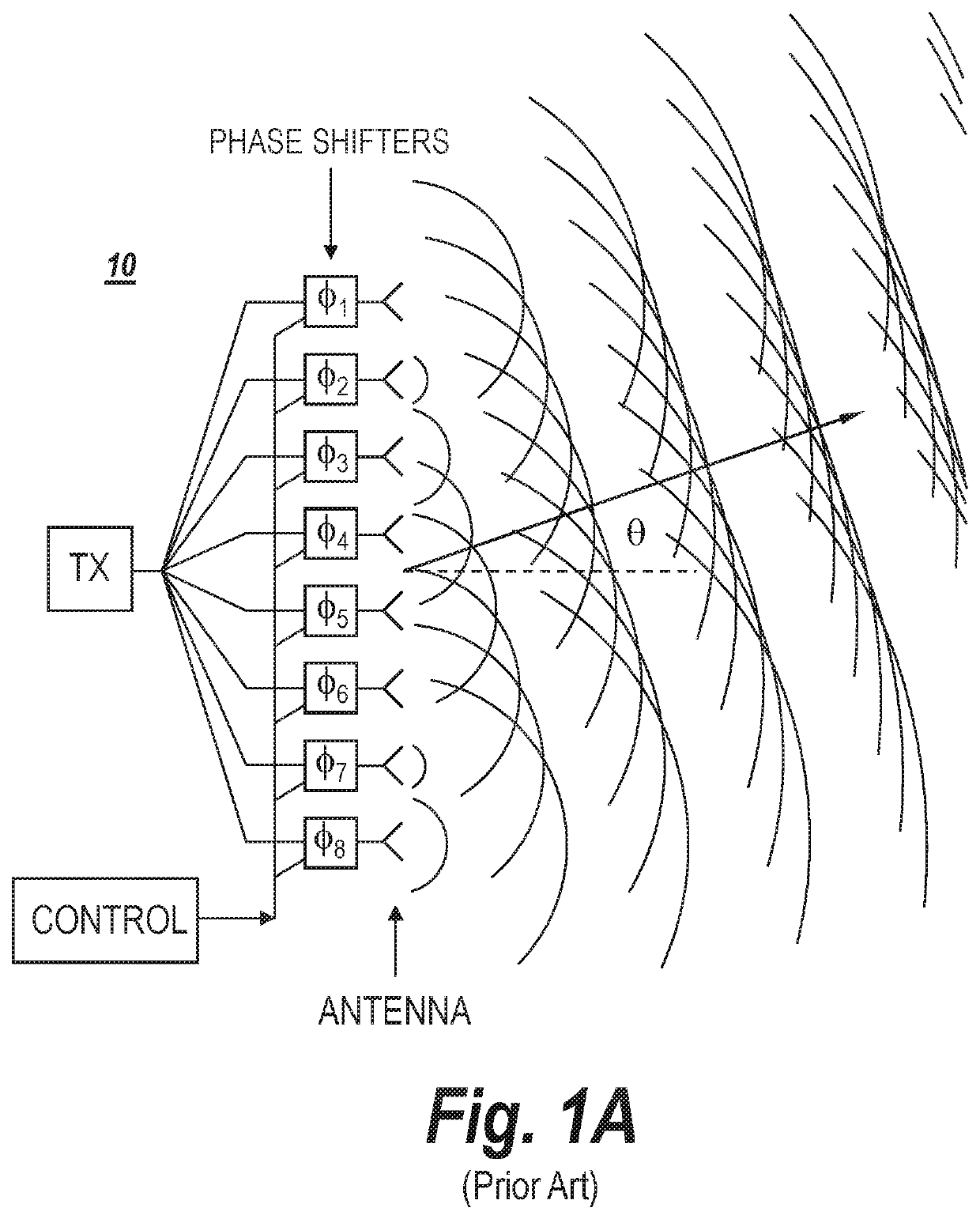
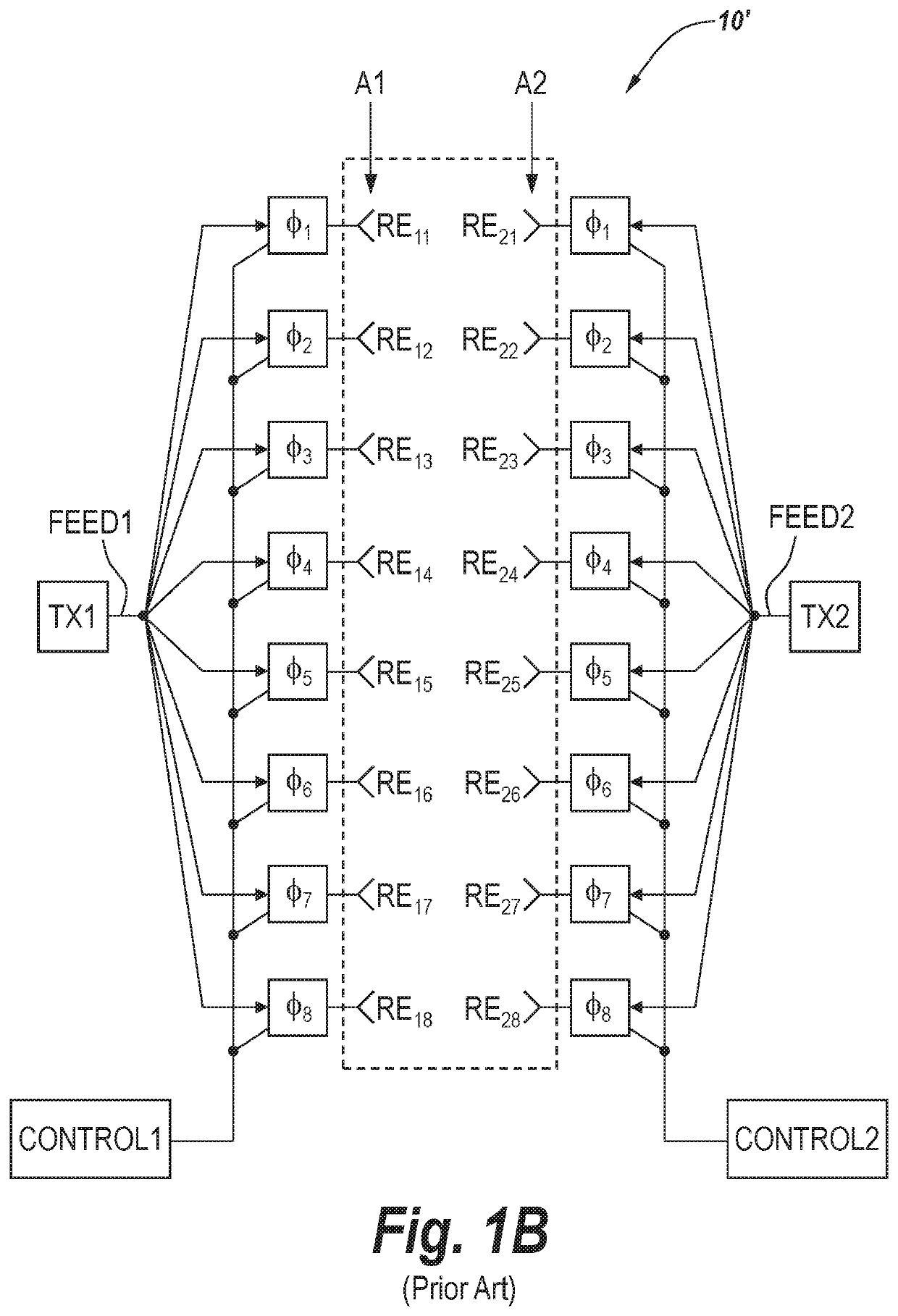
REFERENCE TO PRIORITY APPLICATIONS[0001]This application is a continuation-in-part of U.S. application Ser. No. 16 / 013,262, filed Jun. 20, 2018, now U.S. Pat. No. ______, which claims priority to U.S. Provisional Application Ser. No. 62 / 523,386, filed Jun. 22, 2017, the disclosures of which are hereby incorporated herein by reference. This application also claims priority to U.S. Provisional Application Ser. No. 62 / 882,052, filed Aug. 2, 2019, the disclosure of which is also hereby incorporated herein by reference.FIELD OF THE INVENTION[0002]The present invention relates to radio communications and antenna devices and, more particularly, to base station antenna arrays for cellular communications and methods of operating same.BACKGROUND[0003]Phased array antennas can create and electronically steer a beam of radio waves in varying directions without physical movement of the radiating elements therein. As shown by FIG. 1A, in a phased array antenna 10, radio frequency (RF) feed curren...

Claims


Application Information

Patent Timeline
IPC IPC(8): H01Q5/35H01Q9/04H01Q3/36H01Q5/28
CPCH01Q9/045H01Q5/28H01Q5/35H01Q3/36H01Q1/246H01Q21/062H01Q21/24H01Q21/0006H01Q5/30H01Q3/28H01Q3/34
Inventor CHEN, HONGHUIBISIULES, PETER J.SUN, BINLI, YUEMINMEI, XIAZIMMERMAN, MARTIN L.LI, HAIFENGSHAN, LONG
Owner COMMSCOPE TECH LLC
Why Eureka
Eureka Blog
Learn More