Method for checking the functionality of a braking system, and braking system

a technology for braking systems and functionalities, applied in braking systems, vehicle sub-unit features, braking components, etc., can solve problems such as incorrect identification of non-functionalities, and achieve enhanced reliability and robustness of test results, no additional costs, and enhanced robustness in assessment.

Active Publication Date: 2020-11-19
CONTINENTAL TEVES AG & CO OHG
View PDF0 Cites 3 Cited by
  • Summary
  • Abstract
  • Description
  • Claims
  • Application Information

AI Technical Summary

Benefits of technology

[0046]The advantages of an aspect of the invention consist, in particular, in the fact that the influence of the viscosity on the identification of the state of the braking system can be taken into account. The acceptance criteria can be chosen in such a way that the probability of identifying an intact braking system as faulty is lowered to an acceptable level. This results in enhanced robustness in the assessment of the braking system in respect of its correct functioning. Moreover, a servicing recommendation for a change of brake fluid can be given if the viscosity is outside acceptable limits.
[0047]Through the use of the sensors available in the braking system, there are no additional costs. The reliability and robustness of the test results are enhanced by the use of a plurality of sensors and redundant measurements.

Problems solved by technology

As a result, nonfunctioning is incorrectly identified in situations in which the braking system is still functional.

Method used


Image

  • Method for checking the functionality of a braking system, and braking system
  • Method for checking the functionality of a braking system, and braking system
  • Method for checking the functionality of a braking system, and braking system

Examples


Embodiment Construction

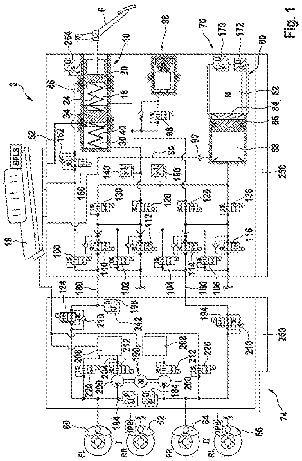
[0053]A braking system 2 illustrated in FIG. 1 comprises a brake pedal 6, by means of which a tandem brake master cylinder 10 is actuated. The tandem brake master cylinder 10 has a first pressure chamber or primary pressure chamber 16, into which a primary pressure piston 20 that is acted upon by a first elastic element 24 can be displaced. The tandem brake master cylinder 10 has a second pressure chamber or secondary chamber 30, into which a secondary piston 34, in particular a floating secondary piston, that is acted upon by a second elastic element 40 can be displaced. In the unactuated state of the primary pressure piston 20, the primary pressure chamber 16 is connected via a hydraulic line 46 to a pressure-medium reservoir 18. In the unactuated state of the secondary pressure piston 34, the secondary pressure chamber 16 is connected via a hydraulic line 52 to the pressure-medium reservoir 18.

[0054]The braking installation or braking system 2 comprises four hydraulically actuata...


PUM


Abstract

A method for checking functionality of a motor vehicle braking system. The braking system has a main module, including: hydraulically actuatable wheel brakes, pairs being assigned to respective brake circuits; at least one electrically actuatable wheel valve per wheel brake sets wheel-specific brake pressures; a pressure provision device actively builds up pressure in the wheel brakes; a pressure-medium reservoir at atmospheric pressure, and an auxiliary module, which has for each of two wheel brakes: a pressure sensor for measuring pressure in a wheel brake line; an open when deenergized isolating valve in the wheel brake line; a pump. At least one variable is measured to assess functionality of the braking system. Using least one acceptance criterion, and checked whether the variable satisfies the acceptance criterion. Determining at least one variable representing the viscosity of the brake fluid, and the at least one acceptance criterion depends on a variable representing viscosity.

Description

CROSS REFERENCE TO RELATED APPLICATIONS[0001]This application is the U.S. National Phase Application of PCT International Application No. PCT / EP2018 / 080457, filed Nov. 7, 2018, which claims priority to German Patent Application No. 10 2017 220 308.0, filed Nov. 15, 2017, the contents of such applications being incorporated by reference herein.FIELD OF THE INVENTION[0002]The invention relates to a method for checking the functionality of a braking system for motor vehicles, which braking system comprises a main module, comprising:[0003]hydraulically actuatable wheel brakes, wherein pairs of said wheel brakes are assigned to respective brake circuits;[0004]at least one electrically actuatable wheel valve per wheel brake, for setting wheel-specific brake pressures;[0005]a pressure provision device for actively building up pressure in the wheel brakes;[0006]a pressure-medium reservoir at atmospheric pressure, and[0007]furthermore comprising an auxiliary module, which comprises for each ...

Claims


Application Information

Patent Timeline
Patent Type & Authority Applications(United States)
IPC IPC(8): B60T17/22B60T13/68B60T13/58
CPCB60T7/042B60T2270/82B60T2270/404B60T13/686B60T2270/402B60T8/4081B60T13/165B60T13/58B60T17/221B60T2270/88B60T2270/406B60T13/145B60T8/885B60T13/161B60T13/166B60T13/745B60T17/22B60T17/222B60T8/90B60T13/146B60T13/662B60T13/741B60T2220/04B60Y2400/81B60Y2400/306B60Y2400/302
Inventor NEU, ANDREASHOLZHERR, BORISBUCH, THOMASBRENN, MARTINBALTES, ANDREAS
Owner CONTINENTAL TEVES AG & CO OHG
Why Eureka
Try Eureka