
Single box type electric wire pushing and pulling machine

Active Publication Date: 2020-11-19
CHEN CHEN YI
View PDF0 Cites 0 Cited by
  • Summary
  • Abstract
  • Description
  • Claims
  • Application Information

AI Technical Summary

Benefits of technology

The invention is a single box electric wire pushing and pulling machine that has an attractive appearance, is small and light, and prevents lubricating oil from leaking out of the machine. This improves the smoothness and speed of wire pushing and pulling while avoiding the possibility of wire twisting and winding inside the machine, which increases efficiency.

Problems solved by technology

1. The conventional electric wire drawing machine comprises two opening box bodies combined into one box, resulting in poor appearance, large volume, increased structural weight, environmental pollution due to easily leakage of the internal lubricating oil and inconvenient use.
2. The conventional electric wire drawing machine comprising two opening box bodies combined into one box has poor overall structural stability and causes an increased spacing between the box assembly and the towing wire pressure wheel assembly, so the traction wire is easily twisted and wound between the box assembly and the towing wire pressure wheel assembly during the wire traction procedure, resulting in the need to interrupt the job to rearrange the traction wire.

Method used


Image

  • Single box type electric wire pushing and pulling machine
  • Single box type electric wire pushing and pulling machine
  • Single box type electric wire pushing and pulling machine

Examples


first embodiment

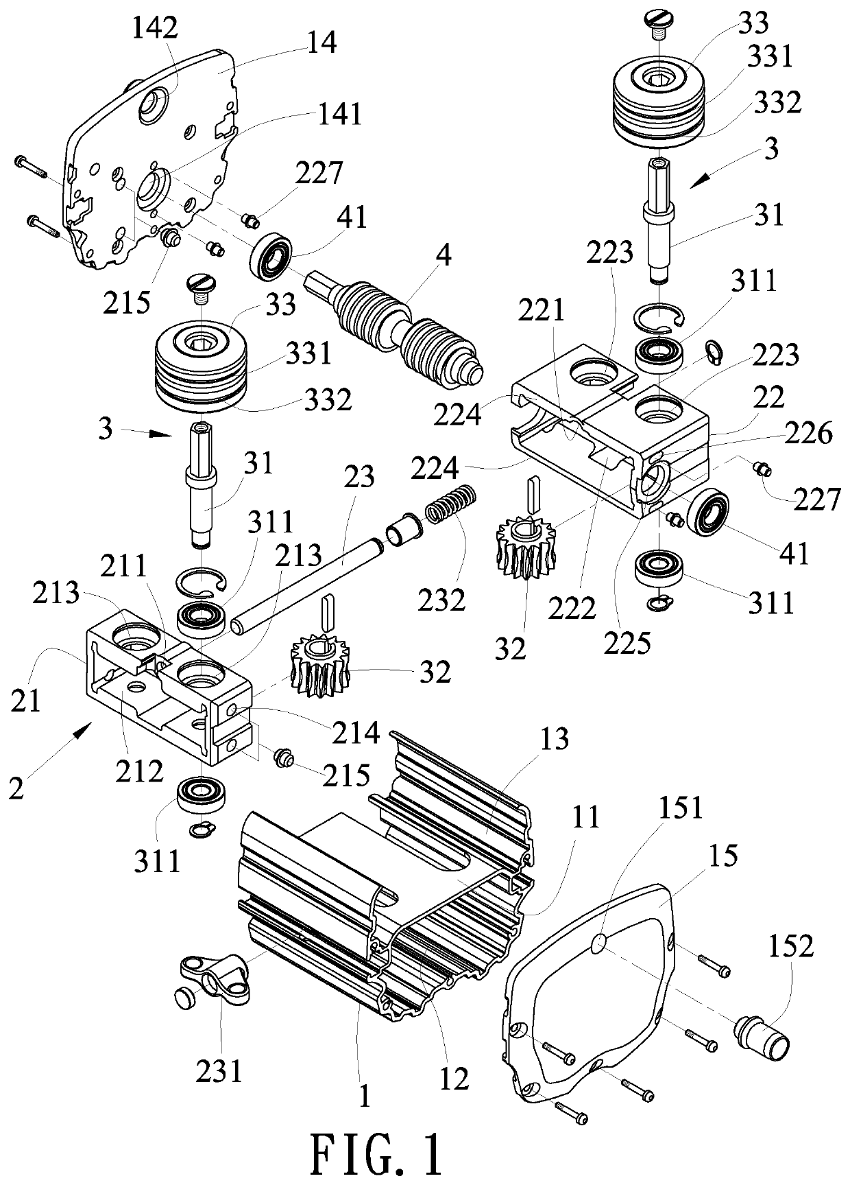
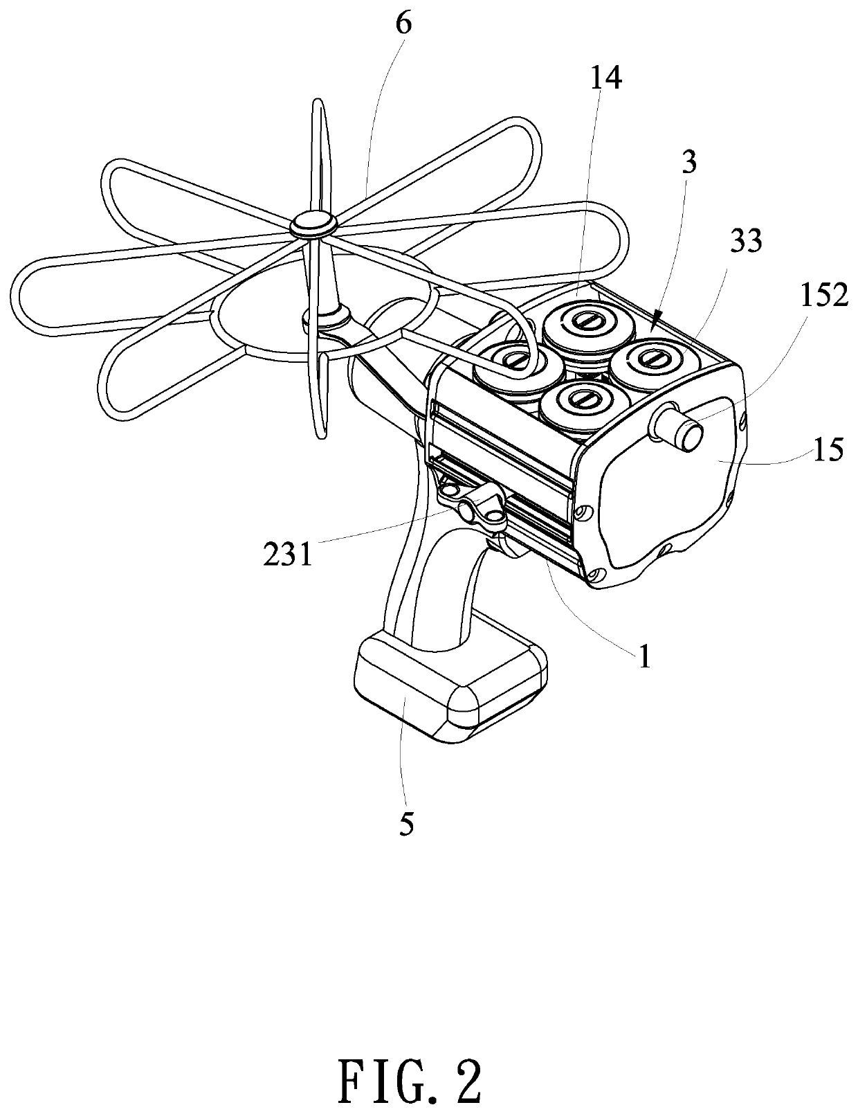
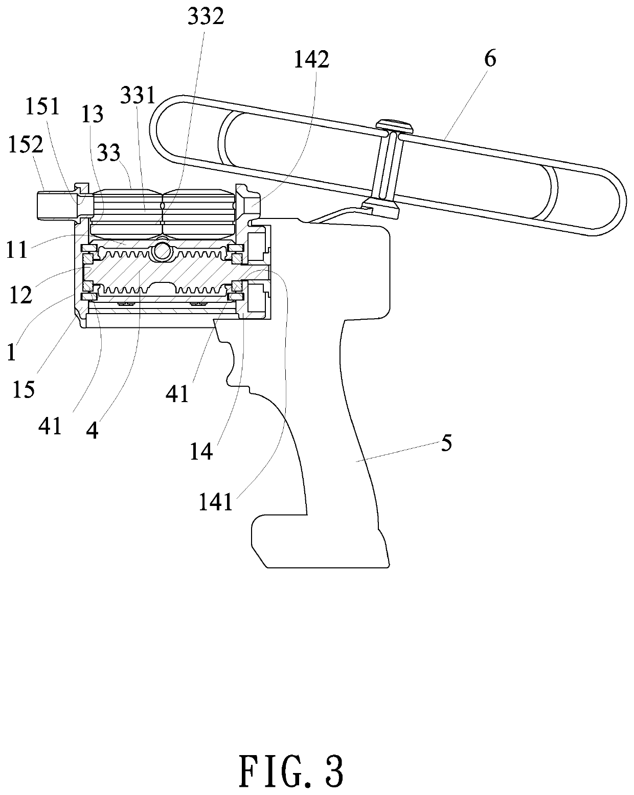
[0017]As showed in FIG. 1 to FIG. 5, a first embodiment for a single box type electric wire pushing and pulling machine according to the present invention is disclosed herein. The single box type electric wire pushing and pulling machine comprises a U-shaped shell (1), an assembling socket (2), four guide wheel assemblies (3) and a gear axle (4).

[0018]The U-shaped shell (1) has a partition (11) to partition the U-shaped shell (1) into a lower chamber (12) and an upper chamber (13), a first panel (14) at a first end thereof and a second panel (15) at a second end thereof. The first panel (14) is provided with a perforation (141) corresponding to the lower chamber (12) and a via hole (142) and corresponding to the upper chamber (13). The second panel (15) is provided with an installation hole (151) corresponding to the upper chamber (13) and a guidance pipe (152) disposed in the installation hole (151).

[0019]The assembling socket (2) is assembled in the lower chamber (12) of the U-sha...

second embodiment

[0024]Referring to FIG. 7, a second embodiment for a single box type electric wire pushing and pulling machine according to the present invention is disclosed. The guidance pipe (152) disposed in the installation hole (151) of the second panel (15) of the U-shaped shell (1) is provided for fast connecting a flexible pipe (153). As shown in FIG. 8, the flexible pipe (153) is convenient for bending and extension at different angles, so that it can be more suitable for different pipelines during the wire pushing and pulling operation, and the convenience of the wire pushing and pulling process is further increased.

third embodiment

[0025]Referring to FIG. 9, a third embodiment for a single box type electric wire pushing and pulling machine according to the present invention is disclosed. The U-shaped shell (1) is provided with a connecting slot (16) at an outside thereof, and a handle (161) is correspondingly inserting into the connecting slot (16), which is convenient for a user to hold the electric rotating tool (5) by one hand and hold the handle (161) by the other hand to perform the wire pushing and pulling operation.

[0026]According to the above description, in comparison with the traditional technique, the single box type electric wire pushing and pulling machine according to the present invention has the advantages as following:

[0027]1. The present invention uses a single box for accommodating the assembling socket, the guide wheel assemblies and the gear axle, which has an aesthetic appearance, a reduced overall volume, a light weight and prevents the internal lubricating oil from overflowing the U-sha...


PUM


Abstract

A single box type electric wire pushing and pulling machine is disclosed herein. It comprises a U-shaped shell having a first panel and a second panel, and an assembling socket accommodated in the U-shaped shell and having a first holder, a second holder, an adjusting rod disposed between the first holder and the second holder for adjusting the spacing, two extension parts respectively extended from an upper end and a lower end of the second holder, a gear axle hole defined by front ends of the two extension parts, two long troughs respectively disposed at a front end and a rear end of the second holder and two limit members correspondingly assembled to the two long troughs for respectively connecting with the first panel and the second panel of the U-shaped shell.

Description

BACKGROUND OF THE INVENTION1. Field of the Invention[0001]The present invention relates to a single box type electric wire pushing and pulling machine which has an aesthetic appearance, a reduced overall volume, a light weight and prevents the internal lubricating oil from overflowing the U-shaped shell so that the smoothness and speed of the wire pushing and pulling operation can be improved, and the situation that the wire is twisted and wound inside the U-shaped shell can be avoided to increase the efficiency of pushing and pulling the wire.2. Description of Related Art[0002]The conventional electric wire drawing machine, for instance, the China patent CN204802742U, issued on 25 Nov. 2015, has disclosed a hand-held electric wire drawing device having two worm wheels. It comprises a worm wheel rod, two opening box bodies opposite to each other and combined to form a box assembly for connecting the worm wheel rod by openings thereof, plural worm wheels of the same size arranged in ...

Claims


Application Information

Patent Timeline
IPC IPC(8): B65H51/10B65H51/32
CPCB65H51/10B65H51/32B65H2701/36B65H2701/376H02G1/083
Inventor WU, YI-HSIANG
Owner CHEN CHEN YI
Learn More